Advanced semiconductor packaging depends on controlled contact during several assembly steps. A force sensor can help detect abnormal loading when a die, substrate, or fixture meets a tool. But a measured total force is not a map of pressure across an entire die, and a sensor alone cannot create closed-loop control. This article explains where force measurement helps, what it cannot prove, and how to assess a compact sensor for a particular press operation.

Editorial cover for force measurement in semiconductor packaging.
1. Where Force Enters the Packaging Process
Die attach, thermocompression bonding, and certain handling or press-fitting steps bring a tool into contact with delicate components. The useful force range and acceptable force-time profile differ from process to process. For one station, the main concern may be excessive peak load; for another, it may be a weak or inconsistent contact event. A recipe has to be validated for the materials, fixture, contact geometry, temperature, and motion used on that specific line.
It is important not to group every advanced-packaging step under the same “press-fit” label. Hybrid bonding, for example, has its own surface-preparation, alignment, and process-control requirements; a load cell used in a separate press operation does not establish suitability for hybrid bonding. The first step is to identify the actual operation and define which force-related quality characteristic the measurement must support. For example, a pressing fixture may need to detect an excessive load before damage occurs, whereas a bonding evaluation may focus on whether contact develops consistently over a defined interval. The validation method should follow that particular goal.
2. Why an In-Spec Total Force May Still Hide a Defect
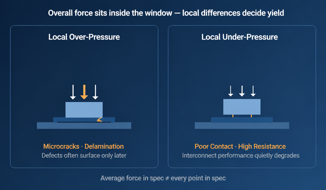
A single-axis force sensor measures the resultant load transmitted through its mounting path. It cannot, by itself, show whether that load is distributed evenly across a die or bonding interface. Tool tilt, fixture compliance, local contamination, and substrate variation can change the contact pattern while the total reading remains inside an accepted window. Depending on the process, a local overload may contribute to damage, while incomplete contact may threaten interface quality.
That is why force monitoring should be paired with appropriate alignment checks and independent quality tests. Where spatial uniformity matters, engineers may need multi-point measurement, pressure-sensitive mapping during qualification, or other validated methods. The diagram below illustrates possible local failure modes; it is not production measurement data and does not imply that one FA104C sensor can locate each over- or under-pressure point. When comparing candidate measurement methods, define the smallest defect or variation that matters and test whether the proposed setup can distinguish it from normal part-to-part variation. That distinction is more useful than choosing a sensor on rated accuracy alone.

Conceptual diagram only; total force monitoring does not measure the full spatial pressure distribution.
3. Monitoring Is Not the Same as Closed-Loop Control
A monitoring system can record peak force or a force-time curve and compare it with process limits. It may reject a part or alert an operator without changing actuator motion. Closed-loop control goes further: a controller reads the sensor signal, compares it with a target, and commands a suitable drive to adjust the applied force. The achievable response depends on the complete chain — sensor, amplifier, sampling, filtering, controller, actuator, mechanics, and commissioning — not on the sensor specification alone.
Fixture heating, changing friction, and part-to-part thickness variation can all affect a contact process. Force data helps quantify those changes, but claims such as “millisecond compensation” or a guaranteed yield improvement require testing on the actual machine. The sensor’s natural frequency is not the usable bandwidth of an installed control loop. Before specifying a target cycle rate, measure the system response under representative operating conditions and confirm stability and repeatability over time.
4. Turning Force Records into Useful Process Evidence
When the equipment records a force result for each operation, engineers can compare distributions across shifts, fixtures, recipes, and material lots. Those records can help identify a change that a simple pass/fail sample might miss. To make the data traceable, store the part or batch identifier with the measurement, limit settings, recipe version, timestamp, and calibration status. If a force-displacement curve is required, synchronize the force and position channels.
A recorded in-window force does not, on its own, certify an electrically sound interconnect or a crack-free package. Set acceptance limits using representative good and defective samples, then compare force-based judgments with independent inspection and reliability results. This turns a sensor reading into one piece of validated process evidence rather than a substitute for package testing. Recheck those limits when the tooling, material stack, or recipe changes: a window established for one configuration may not transfer to another. Maintain a documented revision history so engineers can relate an apparent shift in force distribution to an actual process change.
5. Evaluating the FIBOS FA104C for a Press Station
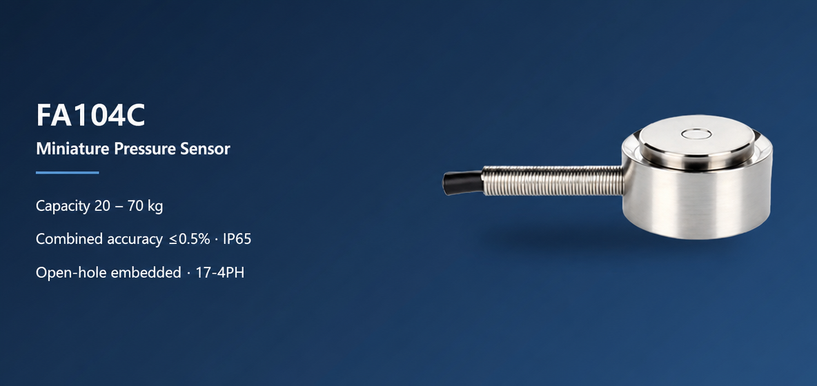
The FIBOS FA104C is a miniature compression force sensor with catalog capacity options of 20, 50, and 70 kg. Its 2026 product sheet lists combined error of ≤0.5% of full scale, natural frequency above 5 kHz, IP65 protection, a 17-4PH stainless-steel spring element, and open-hole embedded installation. These are component specifications, not proof that the sensor is qualified for a particular semiconductor line or that the installed system can run a 5 kHz control loop.

FA104C product visual; check installation and working-force requirements against the official drawing.
Before selecting a capacity, determine the actual working force, possible impact loads, acceptable resolution, and mounting geometry. Confirm that the load is applied to the intended contact surface and that side loads or bending moments are controlled. Then test the entire measurement chain at the required cycle rate and temperature range. For an application review, share your fixture drawing, force range, process timing, and signal-interface requirements with FIBOS; do not infer a packaging yield gain from the catalog alone.