You are here:Home » Blog » How Force Sensors Improve Process Stability in Industrial Automation
How Force Sensors Improve Process Stability in Industrial Automation
Views: 0 Author: Site Editor Publish Time: 2026-05-16 Origin: Site
An automated machine can repeat the same motion while applying a different force on each part. Changes in fit, material stiffness, alignment, or tool condition can alter the interaction between the tool and the workpiece, even when the programmed position remains unchanged.
Force sensors make that interaction measurable. Used with appropriate signal conditioning, process monitoring, and control logic, they help detect unusual cycles and support more consistent operation. The benefit comes from the complete measuring and control system, rather than from installing a sensor alone.
What Does Process Stability Mean?
In everyday production language, stability often means consistent operation. In statistical process control, it has a more specific meaning: the process behaves predictably over time, without evidence of special-cause variation in the characteristics being monitored. A few acceptable parts or a steady force display do not establish that condition.
Stability and capability are different questions. Stability concerns behavior over time; capability concerns how a stable process relates to specification limits. Cp and Cpk help assess capability under appropriate assumptions. They do not replace control charts or establish stability by themselves. Force data can contribute to both investigations, provided the measuring system is suitable for the task.
How Force Measurement Fits into an Automated System
· From Applied Force to a Usable Signal
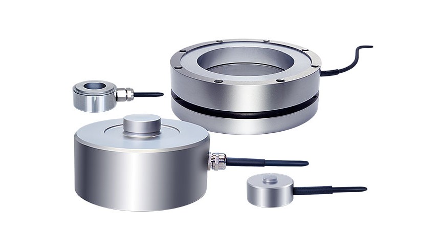
A force sensor converts applied mechanical load into an electrical signal. In a strain-gauge load cell, deformation of the elastic element changes the resistance of bonded strain gauges. Bridge circuitry produces a signal related to the applied load. The sensor’s geometry and mounting determine which loads it is designed to measure.
· Monitoring and Closed-Loop Control Are Different
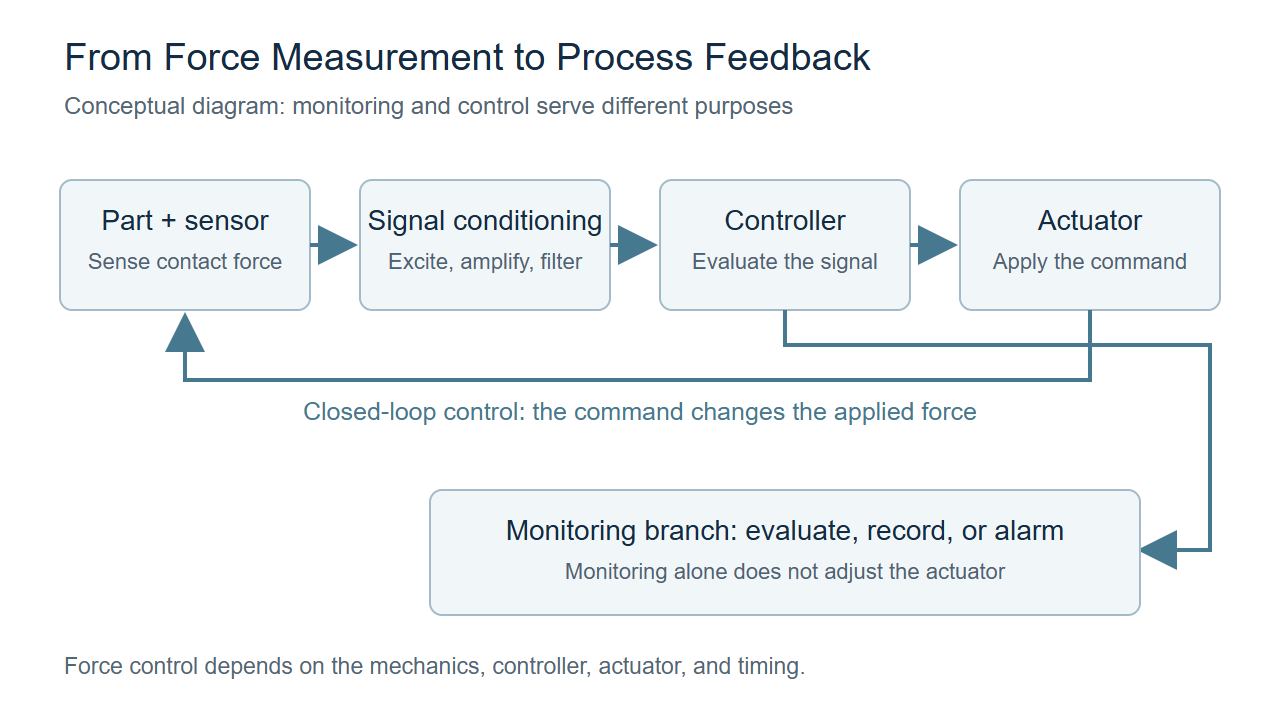
A monitoring system compares measurements with defined limits, records results, or triggers an alarm. A closed-loop controller also uses feedback to adjust an actuator during operation. Connecting a sensor to a PLC input does not automatically create a force-control loop; the actuator, controller, timing, and mechanical behavior must support the intended response.
For an unamplified mV/V bridge sensor, compatible excitation and signal conditioning are required. Voltage, current, and digital outputs may be available through different sensor variants or external electronics. Confirm the actual configuration rather than assuming that every sensor includes an amplifier or communication interface.
How Force Sensors Support More Consistent Production
· Detect Deviations During the Cycle
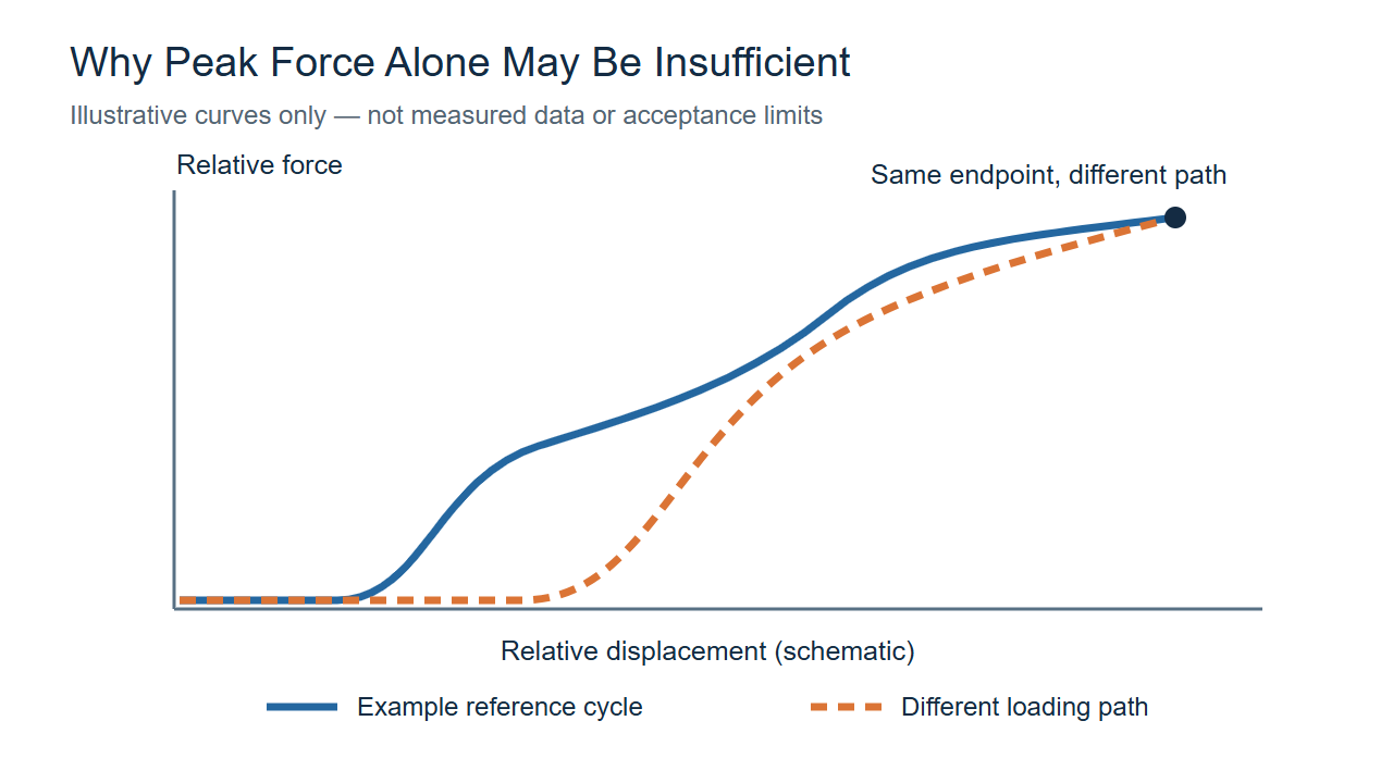
Force measurements can reveal an unexpected contact, a missing component, an unusual insertion event, or an excessive clamping load. Detection requires a defined evaluation window and suitable limits. A peak value alone may miss a defect that appears earlier in the cycle or at a different position.
· Adjust Force Where the Process Allows It
In a suitable press or contact-control application, feedback can be used to approach and maintain a target force. The controller must account for contact stiffness, actuator response, and delay. Aggressive settings or excessive filtering can produce poor settling or oscillation, so the loop must be tuned and verified on the actual machine.
· Track Changes Across Repeated Cycles
Trends in peak force, contact position, or force at a defined displacement can help flag process changes for investigation. Possible causes include tool wear, lubrication changes, material variation, or alignment. A changed force trace is evidence of a changed condition, not a diagnosis by itself. Confirm the cause before assigning a maintenance action.
· Link Measurements to Part and Recipe Records
Recording the recipe, part identifier, evaluation result, and selected force features makes later investigation more useful. Compare like-for-like production conditions and keep measurement settings under change control. Combining unrelated recipes in one trend can hide the source of variation.
Applications That Benefit from Force Feedback
· Press-Fit and Insertion Operations
For joining operations, correlate force with displacement instead of relying only on the final force. The curve can show when contact begins, how resistance changes during travel, and whether the intended end position is reached. Evaluation limits should be developed from the actual part design, process trials, and independent checks of acceptable and defective assemblies.
· Robotic Contact and Assembly
Force feedback can support contact detection, insertion, and controlled tool interaction. Use a single-axis sensor when the task is adequately described by one force direction; consider a multi-axis design when other force components or moments matter. Check coordinate alignment, tool loads, and combined-axis limits. Ordinary force feedback alone does not establish a safety-rated protective function.
· Clamping, Sealing, and Component Testing
Clamping-force monitoring can help detect insufficient or excessive holding force. Sealing and joining processes may also depend on temperature, dwell time, and geometry, so force alone does not establish seal quality. In component testing, define whether the required result is a peak force, a force at a specified position, or a complete load–displacement response.
Implementation Checklist: From Sensor Selection to Validation
· Define the Force Range and Decision Criteria
Specify normal loads, preload, credible peaks, impact, and cyclic duty, together with the smallest force change that matters. Select capacity and protection from those conditions. There is no universal rule that the working load must be 60–70% of full scale. Safe overload is a protection limit, not an extension of the calibrated measuring range.
· Design a Controlled Mechanical Load Path
Follow the selected sensor’s mounting instructions. Control alignment, support flatness, contact geometry, and mounting torque. Unintended parallel load paths can bypass the sensor; side loads, bending, and cable forces can distort the result. Test the installed assembly rather than relying on a bench reading alone.
· Match Bandwidth, Sampling, and Filtering
Identify the fastest force event that must be captured. Sensor dynamics, fixture stiffness, amplifier bandwidth, sampling, and filtering all affect the measured waveform. Sampling rate is not sensor bandwidth, and a high data rate cannot recover detail already lost in the mechanical or analog signal path. For force control, include communication and computation delays in the review.
· Check Environmental and Electrical Conditions
Review temperature effects, moisture exposure, vibration, shielding, grounding, and cable movement. Distinguish the operating temperature range from the compensated range. A quoted IP rating or digital interface does not by itself resolve installation-related drift, electrical noise, or connection problems.
· Validate the Measuring Chain and Process Limits
Verify zero, scaling, and repeatability across the relevant operating range with an appropriate reference. Check the sensor and electronics together, then challenge the installed process with known conditions. Set calibration and inspection intervals according to use, history, and measurement risk; there is no single interval for every sensor.
For an equipment inquiry, share the load direction, normal and peak forces, installation drawing, environment, and required controller connection. This gives the supplier a practical basis for assessing the sensor structure and measuring chain before samples are ordered.
From Force Data to Process Improvement
Force sensing is most useful when each measurement leads to a defined decision: accept or investigate a cycle, adjust an actuator, or review a developing trend. Establish a baseline, validate the limits, and verify improvement using production evidence. Better visibility supports process improvement, but it does not guarantee defect prevention or statistical stability on its own.
Frequently Asked Questions
1. Does installing a force sensor make a process stable?
No. The sensor supplies information. Stability depends on the process, the measuring system, and the actions taken in response. Evaluate behavior over time and confirm that the chosen controls address the actual sources of variation.
2. Why measure force and displacement together?
The same final force can occur at different positions or follow different loading paths. Combining force with displacement provides more context for evaluating insertion, contact, and joining behavior than a single peak value.
3. Can force sensors measure fast-changing loads?
Yes, when the selected sensor, mounting, electronics, and acquisition settings provide the required response. Review the complete system bandwidth and event duration instead of selecting by sampling rate alone.
4. Can a force limit replace a machine safety function?
An ordinary measurement threshold should not be assumed to provide a safety-rated protective function. Process overload detection and protective machine safety have different design and validation requirements.
5. How often should the force-measurement system be checked?
Use the manufacturer’s guidance and the application’s operating history to set an interval. Overload events, fixture changes, unexplained drift, or repair can justify an additional check before production resumes. Include wiring, mounting, zero, and the relevant measuring range in the review.