In modern electric vehicle (EV) development laboratories, one scene appears again and again:
A high-speed electric motor rotates on a test bench. A dynamometer applies controlled loads. Sensors collect thousands of data points every second. Engineers analyze torque curves, efficiency maps, and power performance before a motor design is approved for production.
Behind every important decision is one critical measurement:
Actual shaft torque.
The accuracy of this measurement directly affects motor efficiency evaluation, powertrain optimization, thermal analysis, and durability testing.
This is why a dynamic torque sensor for electric motor testing has become an essential component in EV motor test benches.
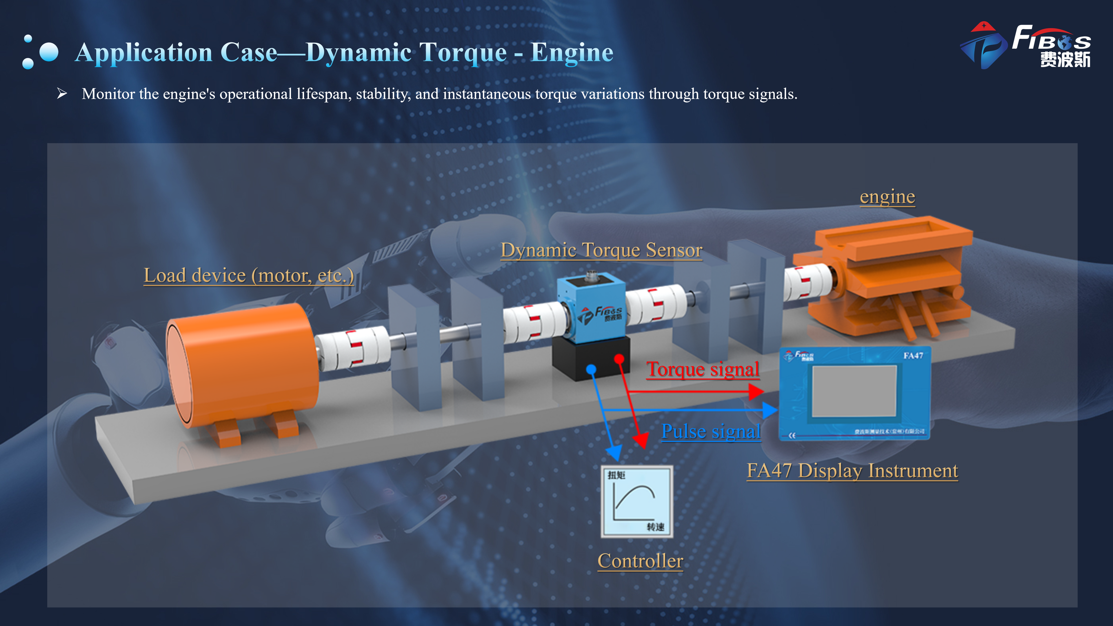
![Dynamic Torque Sensor engine]()
Why EV Motor Test Benches Require Dynamic Torque Sensors
Electric motor testing has become significantly more demanding compared with traditional engine testing.
Modern EV motors operate with:
Higher rotational speeds
Rapid torque changes
Frequent acceleration and deceleration cycles
Regenerative braking conditions
Strict efficiency requirements
During an electric motor test, engineers need accurate measurement of:
Shaft torque
Rotational speed
Mechanical output power
Torque ripple
Efficiency performance
A conventional static torque measurement system may be sufficient for slow or stationary applications, but it cannot capture the real-time changes that occur during motor operation.
For EV powertrain validation, engineers usually require a:
Dynamic rotary torque sensor.
Unlike static torque sensors, a dynamic torque sensor measures torque directly on a rotating shaft while the system is operating.
It provides real-time data during:
Motor acceleration
Load changes
Regenerative operation
High-speed rotation
Efficiency mapping
How Does a Dynamic Torque Sensor Measure Rotating Torque?
A dynamic torque sensor works based on the principle of torsional deformation.
When torque is applied to a rotating shaft, the shaft experiences a small twisting deformation.
Although this deformation is extremely small, it can be accurately detected using strain gauge technology.
The measurement process is:
1. Torque creates shaft deformation
When rotational force is transmitted through the shaft, the elastic element twists slightly.
2. Strain gauges detect the deformation
Precision strain gauges attached to the elastic shaft detect changes caused by torsional stress.
3. The signal is converted into torque data
The sensor electronics process the strain signal and convert it into a measurable torque output.
4. Data is transmitted during rotation
The sensor continuously outputs torque information while the shaft is rotating.
This allows engineers to measure actual transmitted torque between:
Electric motor
Gearbox
Load machine
Dynamometer system
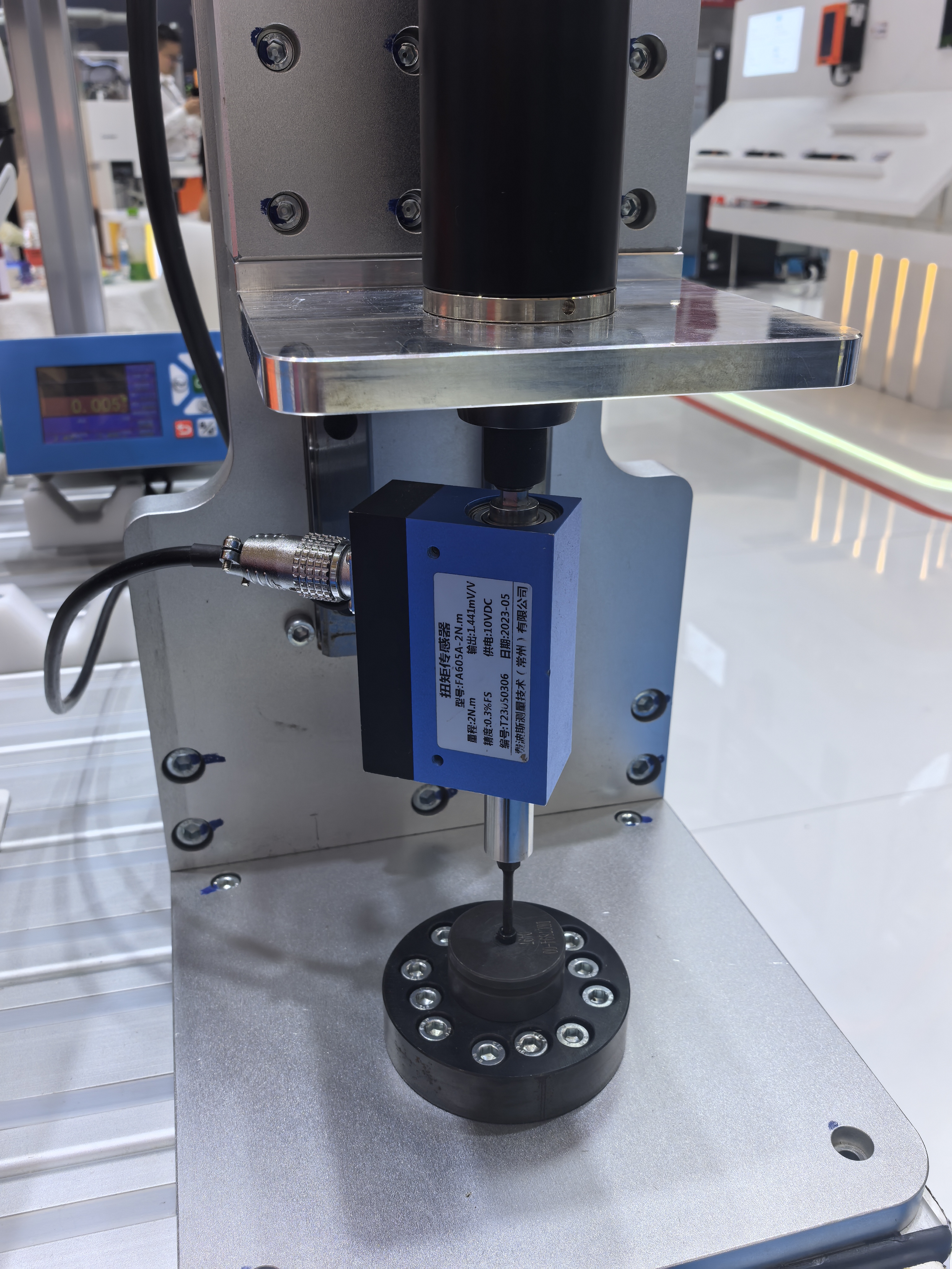
![Dynamic Torque Sensor]()
Why Non-Contact Torque Sensors Are Preferred for High-Speed Applications
A major challenge in rotary torque measurement is transferring electrical signals from a rotating shaft.
Traditional designs often use slip rings.
Although slip-ring systems can work, they have several limitations:
Modern non-contact torque sensors solve this problem by transferring signals without physical contact.
Advantages include:
✓ No brush wear
✓ Reduced electrical noise
✓ Higher reliability
✓ Longer service life
✓ Better suitability for continuous operation
FIBOS non-contact dynamic torque sensors use strain gauge measurement technology combined with contactless signal transmission, providing stable torque measurement for rotating applications.
For example, the FIBOS FA640 adopts a shaft-mounted compact structure with non-contact transmission, designed for applications requiring reliable dynamic torque measurement without mechanical contact limitations.
Dynamic Torque Sensor Applications in Electric Motor Testing
Dynamic torque sensors are widely used in:
EV Motor Test Bench
Used for:
Gearbox Testing
Used to evaluate:
Servo Motor Testing
Used for:
Research and Development Laboratories
Used in:
Choosing the Correct Torque Range
One of the most common mistakes is selecting a torque sensor with a much larger capacity than necessary.
Although a larger range appears to provide more safety, it often reduces effective measurement resolution during normal operation.
A practical engineering recommendation is to keep the normal operating torque between 20% and 80% of the sensor's rated capacity whenever possible.
Example
Suppose your motor normally operates around 250 N·m, with occasional peaks reaching 400 N·m.
A 500 N·m torque sensor is generally a better choice than a 1000 N·m model because:
Better effective measurement resolution
Higher usable accuracy at typical operating loads
Improved efficiency map quality
Better sensitivity to torque ripple
For EV powertrain testing, remember to consider both motoring and regenerative braking conditions when selecting the measuring range.
Understanding Overload Capacity
Rated torque and overload capacity are different specifications.
A sensor should be capable of surviving occasional overloads without permanent damage.
Typical specifications include:
Rated Torque
Safe Overload
Ultimate Overload
Mechanical Failure Limit
For example, FIBOS publishes overload information for different dynamic torque sensor models, allowing engineers to evaluate whether a sensor can tolerate transient events during motor startup, emergency braking, or unexpected load spikes.
A suitable overload margin improves equipment reliability while protecting measurement accuracy.
Accuracy: What Does ±0.1% F.S. Really Mean?
Accuracy specifications are often misunderstood.
When a datasheet specifies:
±0.1% F.S.
the "F.S." stands for Full Scale.
For a 500 N·m sensor:
Measurement uncertainty = ±0.5 N·m throughout the full measuring range.
This is why selecting an oversized sensor can reduce practical measurement performance.
If the application normally measures only 40 N·m, using a 1000 N·m sensor may produce unnecessary measurement uncertainty.
Instead of considering accuracy alone, engineers should also evaluate:
Linearity
Hysteresis
Repeatability
Zero stability
Temperature coefficient
Long-term stability
Together, these characteristics determine how reliable the measurement remains over weeks or months of testing.
Rotational Speed Capability
High-speed capability is another critical parameter.
Many modern EV motors operate between:
3,000 rpm
6,000 rpm
8,000 rpm
12,000 rpm or higher
Before selecting a sensor, verify:
Do not assume that a sensor performing well at low speed will maintain the same accuracy at maximum operating speed.
Always evaluate the complete operating condition rather than relying only on the headline RPM specification.
Signal Output and System Integration
A torque sensor must integrate smoothly with the existing test system.
Common output interfaces include:
The best output depends on the existing data acquisition hardware.
When possible, selecting a sensor capable of outputting both torque and rotational speed simplifies data synchronization and reduces system complexity.
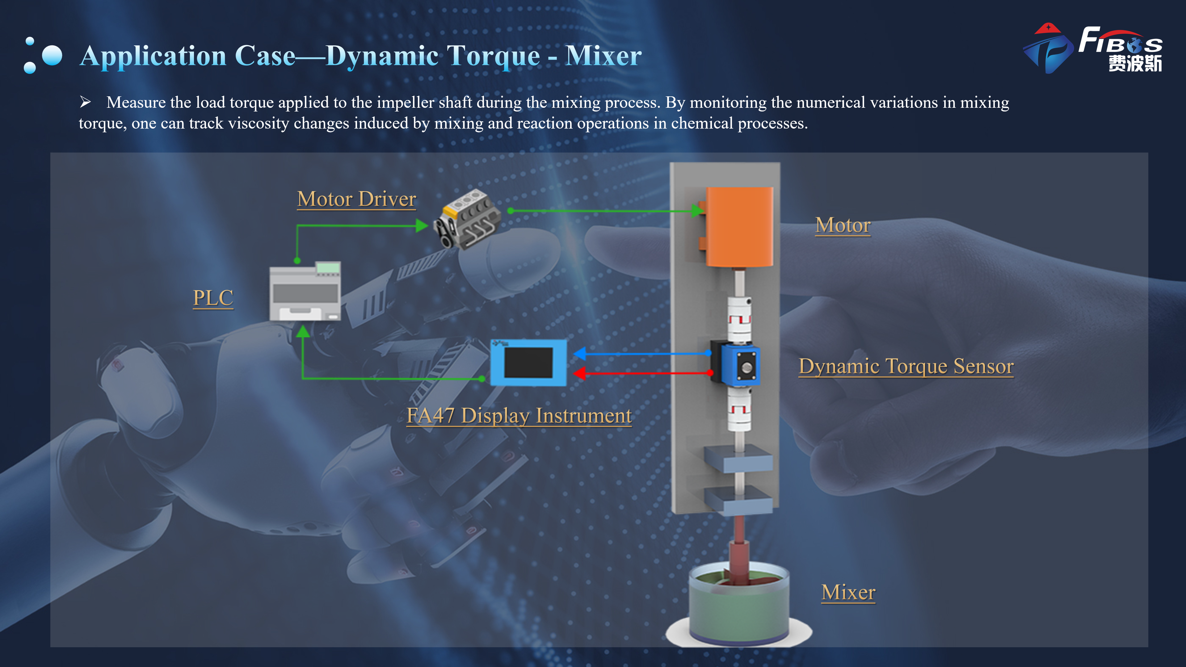
![Dynamic Torque -Mixer]()
FIBOS Dynamic Torque Sensor Solutions
FIBOS Measurement Technology specializes in force and torque measurement solutions for industrial automation, laboratory testing, and electric powertrain development.
Our dynamic torque sensor portfolio supports applications including:
Key product advantages include:
Non-contact signal transmission
High-speed rotary measurement
Compact mechanical design
Multiple communication interfaces
Factory-direct technical support
Custom OEM & ODM solutions
Torque capacities currently cover applications from 0.01 N·m to 1,500 N·m, with selected models supporting rotational speeds up to 12,000 rpm, making the portfolio suitable for everything from micro-motor testing to large electric drive systems.
Recommended Model: FA603 Dynamic Torque Sensor
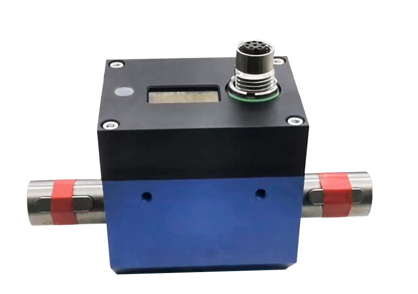
![FA603]()
The FA603 is designed for demanding rotary torque measurement applications requiring both high accuracy and fast response.
Typical applications include:
Key Features
Rated torque options up to 500 N·m
Maximum rotational speed up to 8,000 rpm
Accuracy up to ±0.1% F.S.
Approximately 1 ms response time
Simultaneous torque and speed measurement
Multiple outputs including RS485, analog voltage, and frequency
Its combination of fast response and high accuracy makes it well suited for transient testing and efficiency mapping.
| Specifications | Technique |
| Rated range | 5,10,20,30,50,100,200-500Nm |
| Accuracy | ±0.1,±0.2%FS |
| Zero-point temperature drift | ±0.02%FS |
| Full-scale temperature drift | ±0.02%FS |
| Temperature compensation range | -10~60°C |
| Operating temperature range | -20~75°C |
| Torque output | 10±5kHz,4-20mA,±5VDC,±10VDC,RS485,RS232,CAN |
| Supply voltage | 12-24VDC |
| Supply current | <100mA |
| Electrical connection | 8-Pin |
| Overload protection | 200%FS |
| Materials | Shaft material: 17-4PH stainless steel; housing: aluminium |
| Options |
|
| Speed measurement | Maximum speed: 15,000 rpm, 60 pulses,4-20mA,5V/TTL,±5VDC,±10VDC, RS485,RS232, CAN |
Recommended Model: FA640 Non-Contact Dynamic Torque Sensor
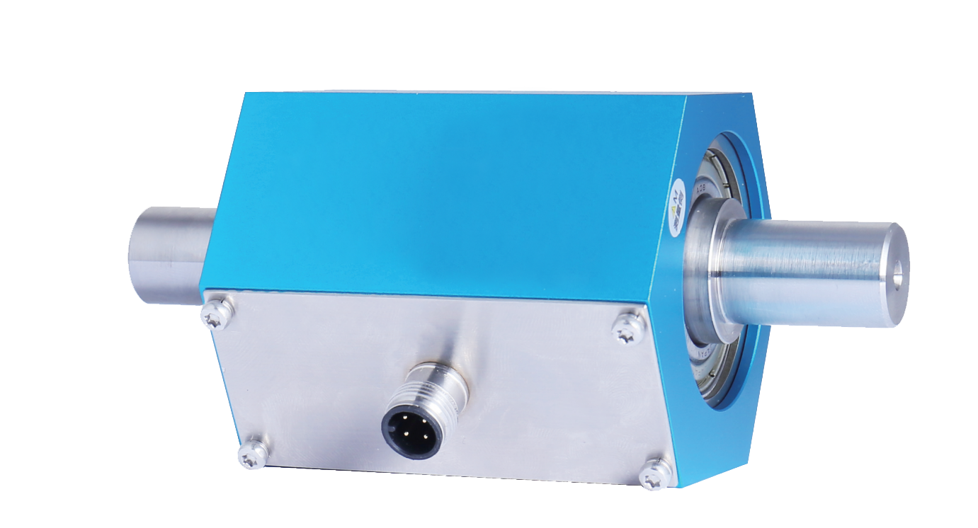
![640]()
The FA640 is optimized for compact rotary measurement applications where reliability and long service life are priorities.
Typical applications include:
Key Features
Torque range from 0.2 to 200 N·m
Non-contact signal transmission
Compact shaft-mounted structure
RS485, ±5 V, and ±10 V outputs
Stable performance during continuous operation
Suitable for high-speed rotary applications
Its compact design makes it an excellent choice for laboratories with limited installation space while maintaining dependable measurement performance.
| Specifications | Technique |
| Capacity | 1/2/5/10N.m |
| Accuracy | 0.5%FS |
| Output signal | ±5VDC,±10VDC,RS485 |
| Supply voltage | 12~28VDC,24~28VDC |
| Max.power loss | ≤7OmA |
| Max. working torque | 150%FS |
| Max. ultimate torque | 200%FS |
| Breakaway torque | 300%FS |
| Ambient temp. | -10~60°C |
| Ambient humidity | 0%–95% RH (non-condensing, no condensation) |
| Shell | 6061 Aluminium |
| Axis | LY12 aluminium (≤2 Nm); stainless steel (>2 Nm) |
| Anti-vibration | 10g(20...2000Hz) |
| Shock resistance | 500g/ms |
| Short-circuit protection | Permanent |
| Inverse pole protection | No damage, but not working |
| Insulation resistance | ≥100MΩ 500VDC |
| Insulation strength | 500VAC |
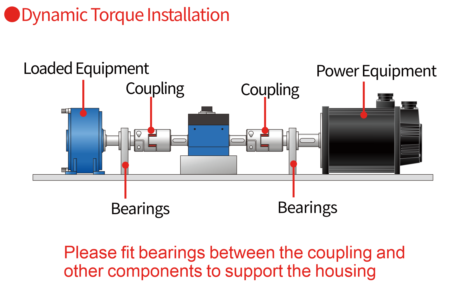
Installation Best Practices for Dynamic Torque Sensors
Even the highest-accuracy torque sensor cannot deliver reliable results if it is installed incorrectly.
In most motor test benches, measurement errors are caused not by the sensor itself, but by mechanical misalignment, improper wiring, or inadequate system integration.
Following good installation practices helps ensure long-term measurement stability and protects the sensor from unnecessary mechanical stress.
![Dynamic Torque Installation]()
Proper Shaft Alignment
Correct shaft alignment is one of the most important factors affecting measurement accuracy.
Poor alignment introduces bending moments and additional radial forces that were never intended to be measured.
Instead of recording pure torque, the sensor receives unwanted mechanical loads that may cause:
Measurement drift
Reduced repeatability
Increased bearing wear
Excessive vibration
Shortened service life
For best results:
Align motor, torque sensor, and dynamometer on the same centerline.
Verify alignment with precision tools before testing.
Recheck alignment after transportation or maintenance.
Proper alignment not only improves accuracy but also extends the life of the entire drivetrain.
Why Choose FIBOS Dynamic Torque Sensors?
Selecting a torque sensor is not only about specifications—it is also about choosing a partner that understands industrial measurement challenges.
FIBOS Measurement Technology has been dedicated to force and torque measurement since 2017, providing factory-direct solutions for customers worldwide.
Our products are widely used in:
Factory-Direct Manufacturing
Working directly with the manufacturer provides several advantages:
Custom Engineering Support
Every test bench is different.
FIBOS supports project-based customization, including:
Custom torque ranges
Special shaft dimensions
Customized mounting interfaces
Multiple communication protocols
OEM and ODM development
Integration support for automated test systems
Our engineering team works closely with equipment manufacturers, system integrators, and research institutions to develop application-specific measurement solutions.
Comprehensive Product Portfolio
Beyond dynamic torque sensors, FIBOS offers a complete range of industrial sensor products, including:
Load Cells
Force Sensors
Multi-Axis Force Sensors
Weighing Modules
Torque Sensors
Signal Amplifiers
Measurement Indicators
This allows customers to source compatible measurement components from a single supplier.
Global Technical Support
FIBOS supports international customers with:
Whether you are developing a new EV powertrain test bench or upgrading an existing dynamometer system, our engineers are ready to help identify the most suitable torque measurement solution.
Frequently Asked Questions
1. What is a dynamic torque sensor?
A dynamic torque sensor measures the torque transmitted through a rotating shaft while the shaft is in motion. Unlike static torque sensors, it continuously captures real-time torque data during rotation, making it suitable for electric motor testing, gearbox validation, and industrial automation.
2. Why is a dynamic torque sensor preferred for EV motor testing?
Electric vehicle motors operate under rapidly changing speeds and loads. Dynamic torque sensors accurately capture transient torque, regenerative braking events, and efficiency maps, providing reliable data for motor development and validation.
3. How do I choose the correct torque range?
Select a sensor whose normal operating torque falls between approximately 20% and 80% of its rated capacity. This helps maximize effective measurement accuracy while maintaining sufficient overload protection.
4. Can dynamic torque sensors measure both torque and speed?
Yes. Many rotary dynamic torque sensors provide both torque and rotational speed outputs, allowing engineers to calculate mechanical power and motor efficiency more accurately.
5. What outputs are commonly available?
Depending on the model, FIBOS dynamic torque sensors support:
Multiple interface options simplify integration with PLCs, DAQ systems, industrial controllers, and laboratory software.
6. Can FIBOS provide customized torque sensors?
Yes. FIBOS offers customized solutions for OEM equipment manufacturers and system integrators, including special torque ranges, shaft dimensions, communication interfaces, and application-specific designs.