You are here:Home » Blog » Miniature Force Sensors: How They Work and How to Choose One
Miniature Force Sensors: How They Work and How to Choose One
Views: 0 Author: Site Editor Publish Time: 2026-10-26 Origin: Site
A press-fit station needs to confirm that a small part seats correctly. A connector test must capture insertion and extraction forces. A button test needs to measure contact force inside a fixture with little room to spare. In each case, the sensor must fit the available space while measuring the force that matters.
A miniature force sensor can provide that measurement, but its size is only the starting point. Load direction, mounting, peak force, measurement quality, and the electrical interface all determine whether it will work in the equipment. This guide focuses on strain-gauge miniature force sensors used in industrial measurement and automation.
What Is a Miniature Force Sensor?
A miniature force sensor is a compact transducer that converts an applied mechanical force into an electrical signal. It may also be called a miniature load cell or a small force transducer. Depending on its design, it measures compression, tension, or both. The mounting arrangement must direct the intended force through its sensing structure.
1. Small Size Does Not Always Mean Low Capacity
Miniature describes the physical envelope rather than a universal measurement range. Sensors with similar outside dimensions may have different capacities, stiffness, and overload limits. A low-profile design may save height but require more lateral space, while a narrow cylindrical design may need additional clearance for threads, cables, or a loading tip.
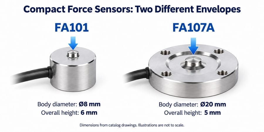
For example, the FIBOS product catalog lists the FA101 with an 8 mm body diameter and a 6 mm overall height, while the FA107A has a 20 mm body diameter and a 5 mm overall height. Both are compression designs, but their mounting details differ. These dimensions describe those catalog models; they are not a size standard for miniature sensors.
Figure 1. FA101 and FA107A body dimensions from the catalog. AI-generated illustrations; not to scale.
2. Force Measurement vs. Fluid Pressure Measurement
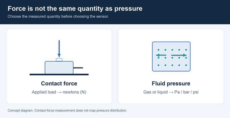
A force sensor measures an applied load, typically expressed in newtons. A fluid pressure sensor measures pressure in a gas or liquid, typically expressed in pascals, bar, or psi. Although pressure and force are related through area, measuring contact force does not automatically provide a contact-pressure distribution. The sensing method and the quantity required must match.
Figure 2. Contact force and fluid pressure are different measured quantities.
How Does a Miniature Force Sensor Work?
1. From Applied Force to an Electrical Signal
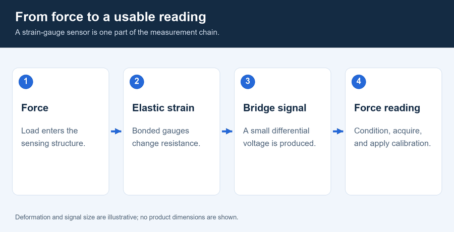
In a strain-gauge sensor, the load produces a small elastic deformation in a metal sensing element. Bonded strain gauges change electrical resistance as the element deforms. A bridge circuit converts that resistance change into a small differential voltage. Within the specified conditions, calibration establishes the relationship between that signal and the applied force.
Figure 3. Applied force becomes a usable reading through sensing, conditioning, and calibration.
2. The Role of Signal Conditioning
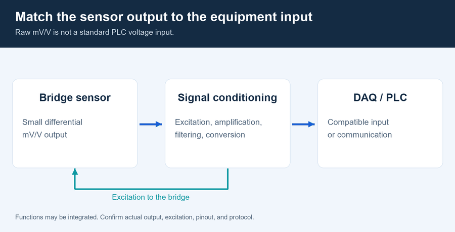
Many bridge-based sensors provide a raw output specified in mV/V. This describes output relative to excitation voltage, not a ready-to-use PLC voltage. Suitable electronics supply excitation, amplify and filter the signal, and convert it into a force reading or a compatible output. Some sensor versions include electronics; others require an external load cell amplifier or a bridge-input measurement module.
Common Miniature Force Sensor Designs
1. Button-Style Compression Sensors
A button-style sensor measures a pushing force applied through a designated loading feature. It can be useful beneath a test head or within a compact compression fixture. The intended contact surface, support area, and cable clearance must remain correct after installation. Miniature button force sensors should be compared by both their mechanical drawing and their measurement specifications.
2. Miniature Tension and Compression Sensors
For a push-pull test, choose a sensor explicitly specified for both directions. Threaded in-line designs can connect between two fixtures, while compact S-type designs provide another arrangement for tension and compression. Not every sensor in either category is miniature, and a compression-only button sensor cannot be assumed to measure tension simply by reversing the display sign.
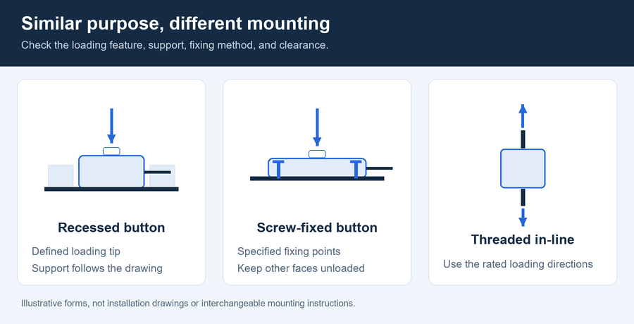
Figure 4. Similar-looking sensors may need different mounting arrangements.
3. How Mounting Features Affect Sensor Selection
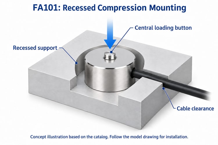
Check which surfaces support the sensor, where the force enters, and which areas must remain free. The FIBOS FA101 catalog drawing shows a recessed installation, while the FA107A drawing shows screw fixing. The FA201 uses threaded connections for tension and compression. These examples illustrate why mounting instructions belong to the model, rather than to every sensor with a similar appearance.
Where Are Miniature Force Sensors Used?
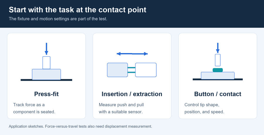
1. Press-Fit and Precision Assembly
A sensor in the pressing load path can track how force changes as a component is assembled. Evaluating force together with displacement can help distinguish an expected assembly pattern from a misaligned part, obstruction, or incomplete seating. Acceptance limits must be developed for the actual parts and process; force measurement alone does not prove assembly quality.
2. Insertion, Extraction, and Pull Testing
Connector and component tests may require force measurements in both directions. The fixtures must grip the test item without adding unwanted bending or rubbing forces. The relevant specification may be peak force, force over a defined travel, or repeatability across cycles. Test speed and alignment should be controlled so that the results can be compared meaningfully.
3. Button, Switch, and Contact Force Testing
A compact sensor can measure the force required to actuate a button or make contact with a small part. Tip shape, loading position, and motion speed affect the test. If a force-versus-travel curve is required, pair force measurement with suitable displacement measurement and synchronized acquisition. The force sensor itself does not measure travel.
Figure 5. Define the task and fixture conditions before selecting the sensor.
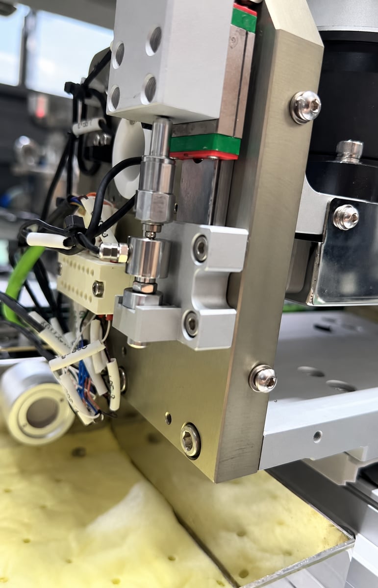
Figure 6. Customer-provided force sensor installation in industrial equipment.
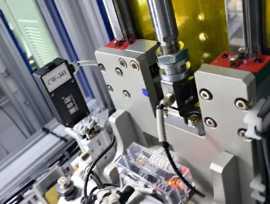
Figure 7. A second customer-provided force sensor installation view.
How to Choose a Miniature Force Sensor
1. Define the Force Direction and Load Path
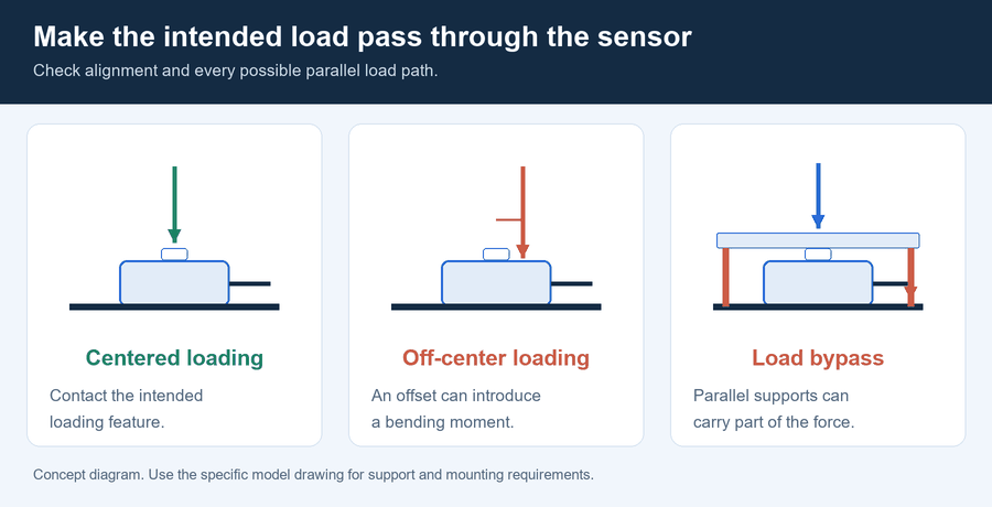
Start with a sketch of the complete assembly. Mark the intended force, the support points, and every contact that could carry load around the sensor. Decide whether you need compression, tension, or both. If forces or moments in several directions are part of the required measurement, evaluate a multi-axis solution rather than expecting a single-axis sensor to report them separately.
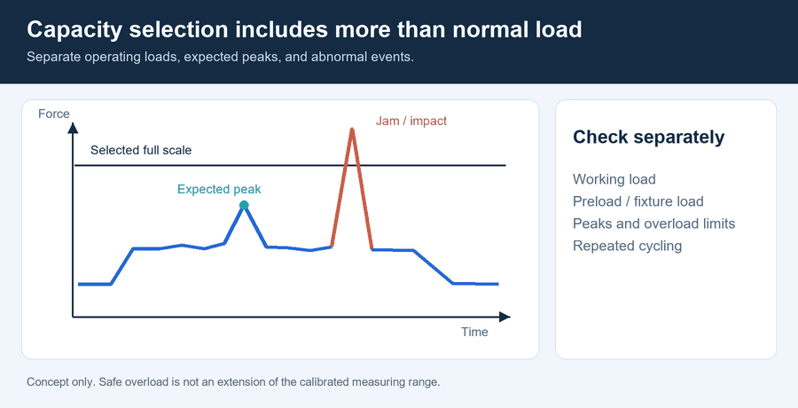
2. Select Capacity for Working and Peak Loads
List the normal operating load, preload or fixture load, expected peaks, and abnormal events such as a jam or impact. Check the selected sensor's permitted loading conditions, overload limits, and fatigue requirements where applicable. There is no single capacity multiplier that suits every mechanism. A safe-overload rating is not an extension of the calibrated measuring range.
Figure 8. Consider normal loads, expected peaks, and abnormal events separately.
3. Match Accuracy, Repeatability, and Resolution to the Task
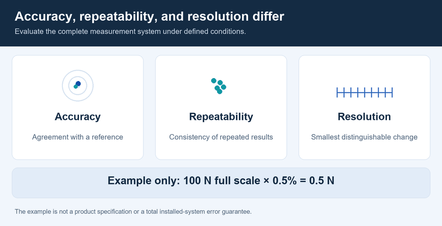
These terms answer different questions. Accuracy concerns agreement with a reference under stated conditions. Repeatability concerns the consistency of repeated measurements under the same conditions. Resolution concerns the smallest change the complete measurement system can distinguish. A display with more decimal places does not automatically deliver better accuracy.
Read whether an error specification is based on full scale or on the reading, and which error components it includes. As an arithmetic example, 0.5% of a 100 N full-scale range equals 0.5 N. That calculation alone is not a guarantee of total installed-system error. Temperature, mounting, signal conditioning, and calibration can add further uncertainty.
Figure 9. Accuracy, repeatability, and resolution describe different measurement properties.
4. Check Dimensions, Environment, and Output Compatibility
Reserve space for the body, mounting hardware, cable exit, bend radius, and any protective features. Then check temperature, moisture, cleaning exposure, vibration, and the actual protection rating of the sensor and its connections. Confirm excitation, output type, input range, filtering, and acquisition rate with the equipment electronics. An available interface on one model or a custom version should not be assumed for the entire product family.
Installation Factors That Affect Measurement
1. Alignment, Contact Surfaces, and Support
Apply force through the intended loading feature and support the sensor as its drawing requires. A surrounding plate should not touch a surface that must remain unloaded, and a hard stop should not bypass the sensor during normal measurement. Contact shape and surface condition matter. Use the specified mounting method and fastening instructions rather than a generic bolt-tightening procedure.
Figure 10. FA101 recessed compression mounting concept based on the catalog. AI-generated illustration; follow the model drawing for installation.
2. Side Loads, Bending Moments, and Overload
An off-center force can create a bending moment as well as an axial load. Side forces, torsion, and cable pull may also disturb the measurement or exceed a mechanical limit. Check these loads individually and in combination using the manufacturer's limits. Protective stops or compliant connections need to be designed so that they protect the sensor without changing the intended measurement path.
Figure 11. Alignment and parallel load paths can change what the sensor measures.
3. Cable Routing and Electrical Noise
Route low-level sensor signals away from power wiring and strong interference sources where practical. Follow the sensor and amplifier instructions for shielding and grounding, and provide strain relief so that cable movement does not pull on the sensor. Confirm pin assignments from the actual drawing; wire colors are not a universal standard across manufacturers or models.
Figure 12. Match the raw or conditioned output to the receiving equipment.
Calibration and Verification Before Use
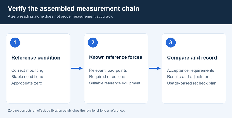
Check the assembled measurement chain rather than the sensor alone. After mounting and warm-up as specified, establish the appropriate reference condition and inspect the zero reading. Apply suitable known reference forces at relevant points and compare the measured values with the acceptance requirements. Verify both loading directions when the application requires them.
Zeroing removes an offset; it does not establish the sensor's sensitivity or prove accuracy across the range. Calibration characterizes the relationship to a reference, while adjustment changes the measurement response. Keep records of the equipment, mounting, conditions, results, and any adjustments. Set recheck intervals according to risk, usage, stability, and applicable quality requirements rather than adopting one interval for every installation.
Figure 13. Verify the installed system using relevant reference forces and documented criteria.
Frequently Asked Questions
1. Can a Miniature Force Sensor Measure Both Tension and Compression?
Yes, if the particular model is designed, mounted, and calibrated for both directions. Confirm the specified range and loading method for each direction. A compression-only design should not be used for a pull test without an explicitly approved arrangement.
2. What Happens If the Sensor Is Overloaded?
Overload can cause a shifted zero, changed sensitivity, permanent deformation, or failure. If a load event may have exceeded a permitted limit, stop relying on the reading until the sensor and installation have been assessed. Returning the display to zero does not demonstrate that the sensor remains within specification.
3. Can a Miniature Force Sensor Connect Directly to a PLC?
It depends on the sensor output and the PLC input. A raw mV/V bridge normally needs compatible bridge-input hardware or an amplifier. A conditioned analog or digital version may connect to a matching input or communication interface, provided that the electrical and protocol requirements agree.
4. Can Miniature Force Sensors Measure Changing Forces?
Strain-gauge sensors can measure changing forces when the sensor, mounting, and electronics meet the required dynamic response. Check the bandwidth of the complete system and the acquisition settings. Natural frequency, sampling rate, and usable measurement bandwidth are different specifications and should not be substituted for one another.
5. What Information Is Needed for a Custom Sensor?
Provide the intended application, force direction, normal and peak loads, available space, mounting drawing, required measurement quality, environment, output interface, and expected quantity. Explain any preload, impacts, side loads, or repeated cycling. A sketch of the real load path is often more useful than a request for a small sensor alone.