Flange torque sensor Product Description |
Incorporating intelligent sensor design principles, with built-in zero-calibration functionality and filtering algorithms
A range of advanced features, including parameter settings and fault diagnosis
Excellent anti-interference capability and high dynamic performance
Up to 14 kHz/s, ensuring greater accuracy in mechanical efficiency measurement
Multiple built-in temperature compensation functions, resulting in low temperature drift
Provides users with high-precision, highly reliable torque measurement solutions
Flange torque sensor Specifications |
Flange Torque Sensor General Specifications Table |
| Code | 50Q | 100Q | 200Q | 500Q | 001R | 002R | 003R | 005R | 010R |
| Measurement range | 50N.m | 100N.m | 200N.m | 500N.m | 1KN.m | 2KN.m | 3KN.m | 5KN.m | 10KN.m |
| Rotational speed range | 0~20000RPM | 0~15000RPM | 0~12000RPM | 0~10000RPM |
| Optional rotational speed | 0~30000RPM | 0~30000RPM | 0~20000RPM | 0~14000RPM | 0~12000RPM |
| Rotor Weight (without rotational speed) | 1.1kg | 1.9kg | 3.8kg
| 6.5kg | 10.9kg |
| Stator Weight | 1.3kg | 1.1kg
|
| Natural Vibration Frequency | ≥2KHz | ≥1KHz
| ≥800Hz |
| Accuracy | 0.1%(System accuracy)Optional 0.05%(System accuracy) |
| Overload Torque | 3 times the overload torque (10 times available on request) |
| Break Torque | 5 times the breaking torque (20 times available on request) |
| Hysteresis | 0.1% 0.03% |
| Non-linearity | 0.1% 0.03% |
| Repeatability | 0.1% 0.02% |
| Torque Resolution | 0.01 N·m (bus data) |
| Geometric Tolerance | Coaxiality tolerance: <0.01 mm Perpendicularity tolerance between the two mounting surfaces: 0.01 mm |
| Rotor-Stator Mounting Deviation | Flat base radial: ≥3 mm (customisable: ≥10–50 mm) Axial: ±3 mm (customisable: ≥10–50 mm) Quarter-circle: ≥5 mm (customisable: ≥10–50 mm) Axial: ±3 mm (customisable: ≥10–50 mm) |
| Dynamic Balancing | G2.5 |
| Zero Drift | 0.00025 |
| Signal Output Frequency | 1 kHz (default) 1 kHz–14 kHz (optional) |
| Signal Output Method | Voltage signal: ±10 V (default); Current signal: 4–20 mA (optional) Voltage signal drive capability: 25 mA; Square wave drive capability: 100 mA Frequency signals: 10±5 kHz, 60±30 kHz, 240±120 kHz (5V TTL square wave) Analogue signal isolation voltage: 1500 V; Square wave signal isolation voltage: 5000 |
| Over-Range Output | Frequency signal over-range output: 1.5 times |
| Second Range | 10%–50% (selectable) |
| Third Range | 20%–80% (selectable; custom) |
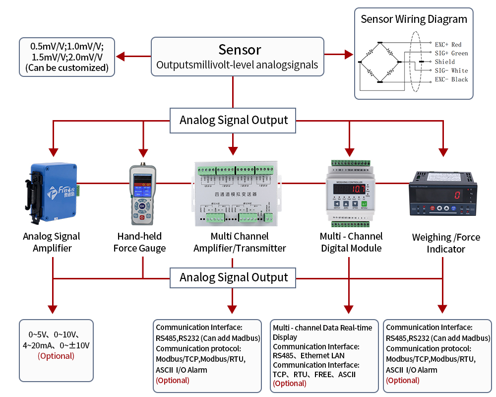
| Data Output Method | RS485, CAN 2.0 (optional), Ethernet (optional) Signal isolation voltage: 5000 V |
| Communication Cable Requirements | RS485 twisted-pair cable, length not exceeding 1 kilometre, terminating resistor 1200 ohms; CAN twisted-pair cable, length not exceeding 40 metres, terminating resistor 1200 ohms; Fibre-optic transmission is available as an option for long-distance applications in environments with high levels of interferenc |
| Over-Range Output | RS485, CAN, Ethernet: 1.5 times the full scale |
| Signal Mid-Value Output | Signal or command: sensor output at optimal operating point (mid-point signal); short-circuit pins 6 and 7 on connector 3 |
| Signal Zeroing | Low-level reset (short-circuit pins 1 and 5 on Connector 3 for 1s) |
| Sensor Software Functionality | Signal reset, secondary calibration, filter parameter setting (34 combinations of filter algorithms and filter frequencies), fault diagnosis, software upgrade |
| Operating Voltage | DC 12V~36V Surge protection: 1500 V |
| System Power | ≤15 W (at 24 V, with a start-up current of 3 A) |
| Nominal(Rated)Temperature | +10°C~+70°C |
| Operating Temperature | -40°C~+85°C |
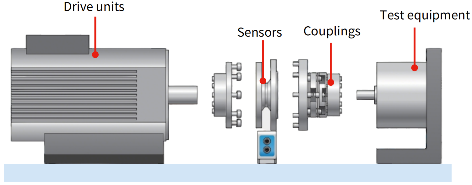
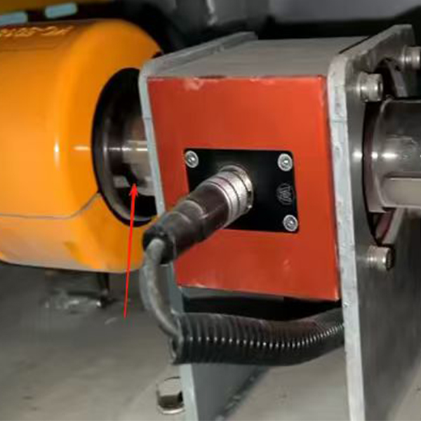
Flange torque sensor Installation |
![FA611 Installation]() |
| Please fit a bearing between the coupling and the other components to support the housing. |
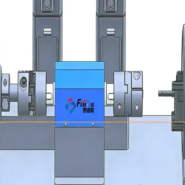
Sensor Styling Suggestions |
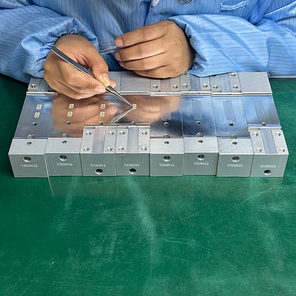
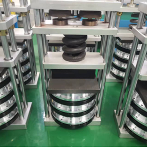
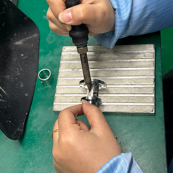
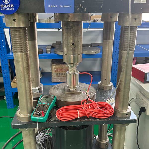
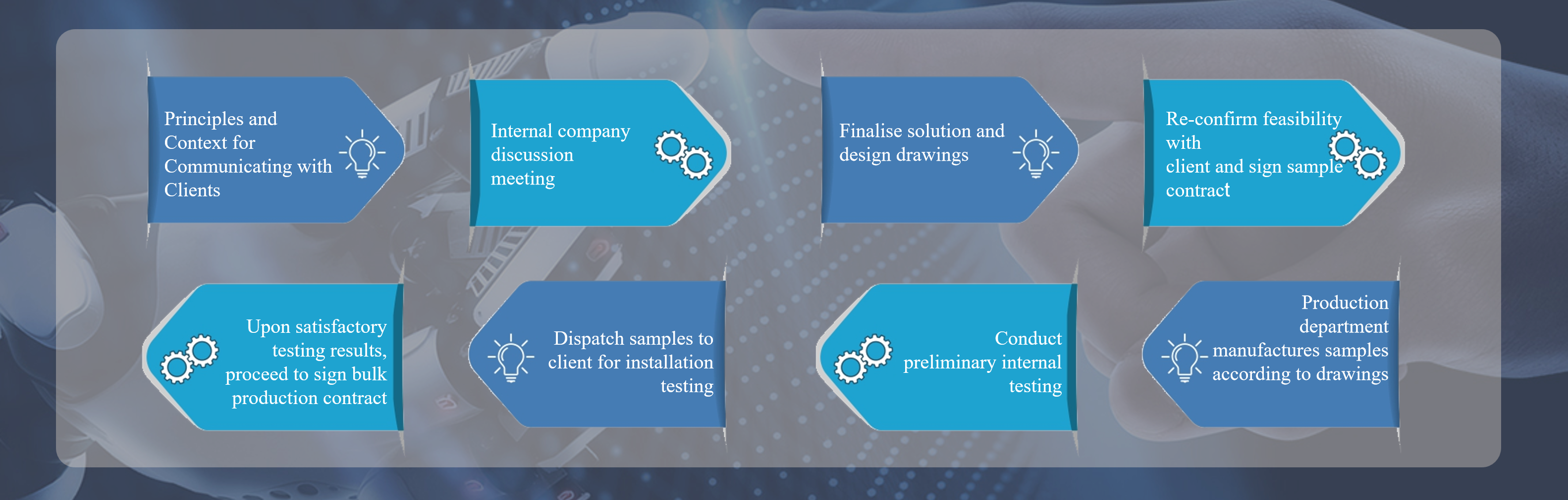
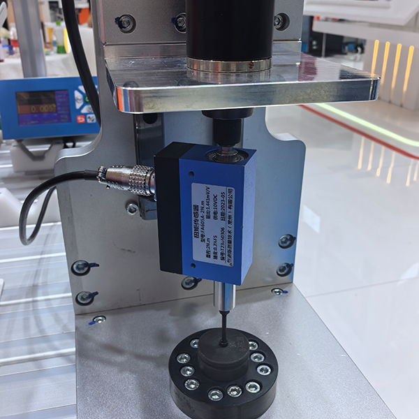
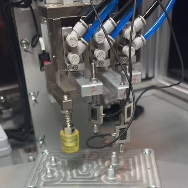
Force sensor manufacturing process |
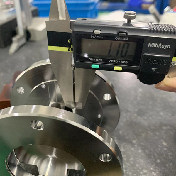
![Incoming Material Inspection]()
01 Incoming Material Inspection
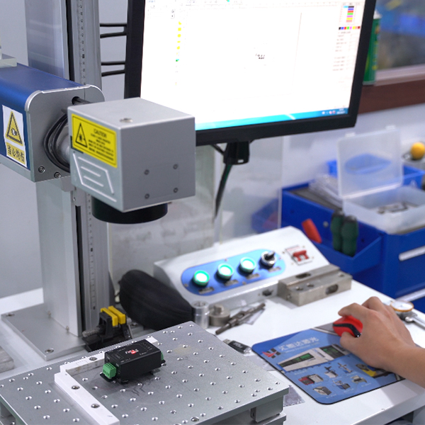
![Laser Marking]()
02 Laser Marking
![Cleaning and Placement]()
03 Cleaning and Placement
![Pressure curing]()
04 Pressure curing
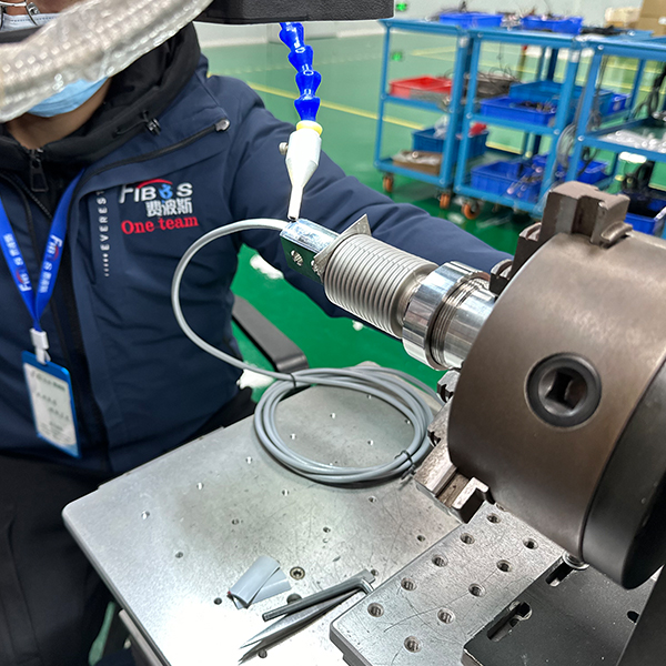
![Bridge Assembly Welding]()
05 Bridge Assembly Welding
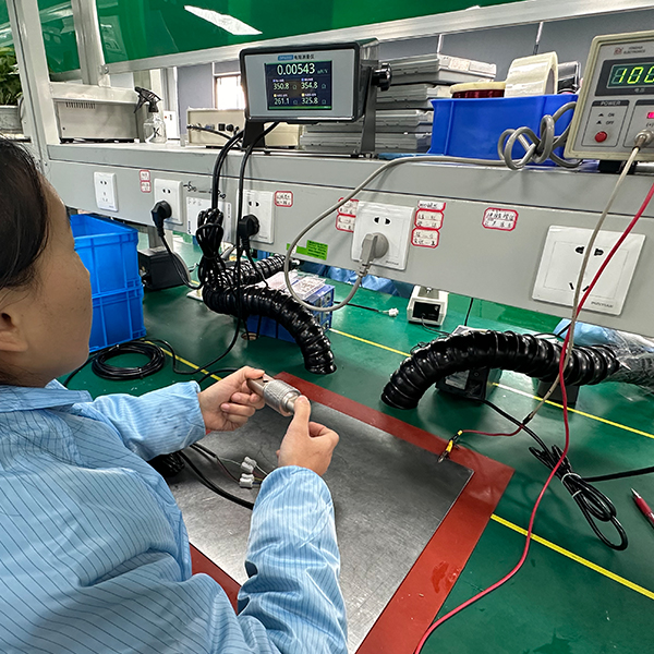
![Test Compensation]()
06 Test Compensation
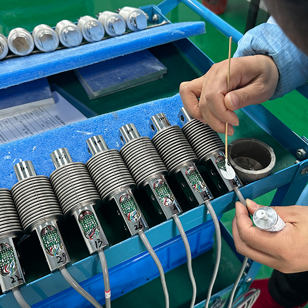
![Adhesive application and curing]()
07 Adhesive application and curing
![Laser welding]()
08 Laser welding
![Finished Product Re-testing]()
09 Finished Product Re-testing
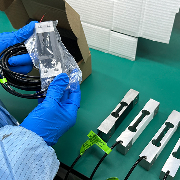
![Cleaning and packaging]()
10 Cleaning and packaging
Sensor Non-standard customisation process |
![Non-Standard Customization Process]()
|
| Fibos possesses a professional technical team capable of developing customized products to meet specific client requirements. Our R&D cycle is seamlessly integrated with our in-house production lines, enabling us to deliver relevant products within a short timeframe. |
Customer case studies for the Torque series |
![Customer case studies for the Torque series (1)]()
Case Studies on Non-Contact Torque Applications
![Customer case studies for the Torque series (2)]()
Case Studies on Static Torque Applications
![Customer case studies for the Torque series (4)]()
Case Studies on Non-Contact Torque Applications
![Customer case studies for the Torque series (3)]()
Case Studies on Non-Contact Torque Applications
![Customer case studies for the Torque series (5)]()
Case Studies on Non-Contact Torque Applications
![Industrial Applications of Micro-Force Sensors]()
Industrial Applications of Micro-Force Sensors
![Industrial Applications of Micro-Force Sensors]()
Industrial Applications of Micro-Force Sensors
![Industrial Applications of Micro-Force Sensors]()
Industrial Applications of Micro-Force Sensors
Frequently Asked Questions about Force Sensors |
Q1: What is the FA611B used for?
A: It is a high-precision flange-type dynamic torque sensor for real-time torque measurement on high-speed rotating machinery like motors, gearboxes, and engines.
Q2: What is its accuracy and speed performance?
A: System accuracy of 0.1%FS (0.05%FS optional), with a sampling frequency up to 14KHz and maximum rotational speed up to 30000RPM.
Q3: What output and communication options are available?
A: Default ±10V voltage output, optional 4-20mA current/frequency outputs; supports RS485, CAN 2.0B, and Ethernet for industrial system integration.
Q4: Is it suitable for harsh industrial environments?
A: Yes. It features strong anti-interference, wide -40℃~+85℃ operating temperature, 3x overload protection (up to 10x customizable), and high isolation voltage.
Q5: Does it have intelligent functions?
A: Yes. Built-in zeroing, filtering, temperature compensation, fault diagnosis, and multi-point calibration for stable, low-drift measurement.
Q6: What power supply does it require?
A: Wide DC 12V-36V input, compatible with common industrial power systems, with ≤15W low power consumption.
Q7: Is it customizable?
A: Yes. Custom torque ranges, overload multiples, installation dimensions, and multi-range settings are available to meet specific application needs.
Q8: Is it easy to commission and maintain?
A: Yes. Dedicated sensor software supports zeroing, calibration, filter setting, and firmware upgrade, simplifying on-site setup and maintenance.
 Russia