A column force sensor, often called a column load cell, measures force along its main axis. If your assembly pushes and pulls, start with a sensor rated for tension and compression and check how both ends attach. If the load is always compressive, check how the force enters the loading surface and how the base is supported. In either case, a capacity match is only the first step: an off-center contact point, a screw that bottoms out, or a fixture that touches the wrong surface can change the reading.
What Is a Column Load Cell, and How Does It Work?
· What Axial Force Does a Column Load Cell Measure?
It measures force along the axis identified on the model drawing. Depending on its rating and mounting design, it may measure compression, tension, or both. Check the load direction arrows before designing the fixture. A cylindrical housing alone doesn't establish the measurement direction, the internal sensing geometry, or the allowable side load.
· How Strain Gauges Convert Axial Load into an Electrical Signal
In a strain gauge design, an axial load slightly deforms the sensing element. The strain gauges change resistance, and a powered Wheatstone bridge converts that change into a differential voltage. A bridge output specified in mV/V expresses the signal change at rated load per volt of excitation. The readout uses a calibration relationship to convert the signal into force, typically displayed in N or kN.
Which Column Load Cell Design Fits Your Application?
| Design | Start here when… | Check on the drawing |
| Compact threaded tension/compression | A linkage must carry both push and pull forces. | Thread size and depth, seating faces, installed length. |
| Compression column or canister | A platen or loading head applies compressive force. | Active end, support face, load introduction hardware. |
| Rocker column for weighing | A scale platform needs a defined load introduction assembly. | Matching fittings, permitted movement, platform restraints. |
· Compact Threaded Column Sensors for Tension and Compression
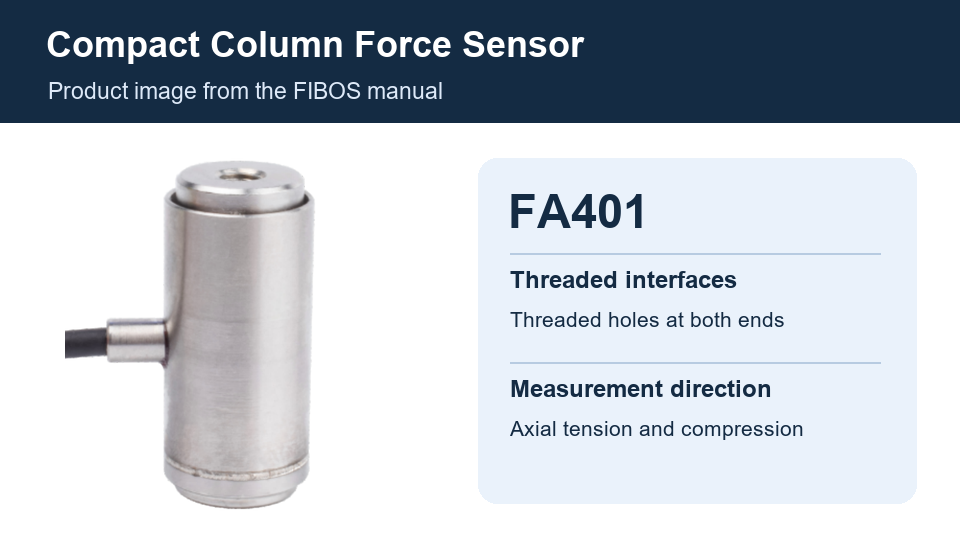
The FIBOS FA401 is a compact example with nominal capacities of 10, 20, 50, 100, and 200 N. Its manual shows threaded holes at both ends and mounting for tension and compression. Use the drawing to check whether both adapters can seat properly and whether the assembled sensor leaves enough travel for the mechanism.

FIBOS FA401 from the product manual. The installation drawing specifies threaded mounting at both ends.
· High-Capacity Compression Column Load Cells and Canister Designs
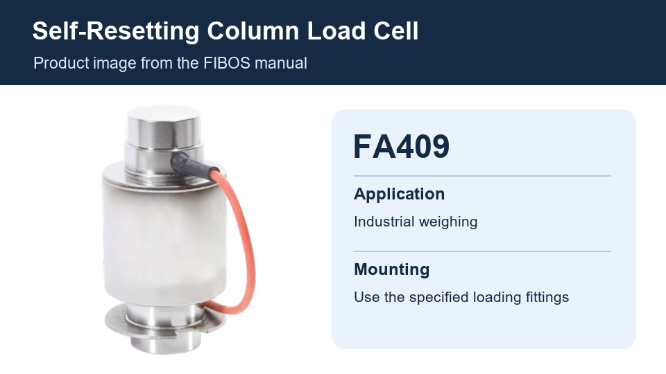
For high compressive forces, look for a design that fits the loading head and support structure as well as the force range. Some canister models have a designated active end and a supported base, with clearance required around the housing. A weighing-specific variant, such as the FIBOS FA409 self-resetting column load cell, uses dedicated load introduction fittings. Check the drawing for the specific variant before assuming it can accommodate movement or accept a particular loading head.

FIBOS FA409 from the product manual. Use the mounting drawing to identify the correct load introduction fittings.
Where Are Column Force Sensors Used?
· Presses and Actuators: Measuring Axial Process Force
On a press-fit station, place the sensor in the force path between the actuator and the workpiece, or in the reaction path under the fixture if the layout supports it. Check the path through the full stroke. A stop or guide that starts carrying part of the load can make the measured force differ from the force at the workpiece.
· Test Fixtures: Measuring Push, Pull, and Compression Loads
For a push-pull bench test, align the specimen grips with the sensor axis and verify the reading in each direction used. For a small-force experiment, record the baseline with the actual fixture installed and compare its variation with the smallest force change you need to detect. A quiet unloaded bench reading alone doesn't show how the setup behaves during a test.
· Industrial Weighing: When to Use a Compression Weigh Module
For a vessel or weighing platform, evaluate the complete support assembly. A compression weigh module can provide defined loading and support interfaces; check how the installation handles thermal movement, restraint, and uneven load distribution. For a vessel, also check whether connected piping transfers part of the load away from the weigh modules.
How Do You Choose the Right Column Load Cell?
· Match the Load Direction, Working Range, and Peak Force
List the smallest useful force, typical working force, and highest expected force in each direction. Include fixture weight or preload where it acts through the sensor, plus peaks from startup, contact, or a jam where relevant. Use the rated range for intended measurement and check the manufacturer's overload limits separately. A safe overload figure does not extend the calibrated measuring range.
· Check Measurement Error at the Smallest Force You Need to Resolve
Suppose an error term is specified as ±0.1% of full scale on a 200 N sensor. That term is ±0.2 N, equivalent to 4% of a 5 N reading. This is an illustrative calculation for one error term, not a prediction of total system error. Compare the tolerance at your working force with the applicable sensor specifications, temperature effects, fixture effects, and readout noise. For measurements held at a steady load, check creep over the actual hold time.
· Check End Interfaces, Mounting Space, and Operating Conditions
Open the dimensional and installation drawings together. Check installed height with adapters, thread depth or loading surface geometry, and clearance for the cable or connector throughout machine travel. Then confirm operating and compensated temperature ranges where specified, ingress protection, and any limits on repeated loading. For dynamic measurements, check the response of the mounted system and the data acquisition chain against the shortest event you need to capture.
How Do You Mount a Column Load Cell to Avoid Measurement Errors?
· Keep the Load Centered and Aligned with the Sensor Axis
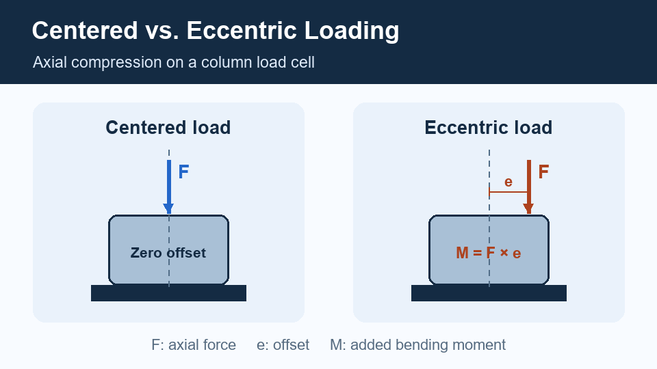
A force parallel to the axis can still act off-center. For example, a 1 kN force offset by 2 mm creates a 2 N·m bending moment at the sensor cross section. This calculation shows the additional moment; it does not tell you the resulting measurement error or whether the sensor can tolerate it. Check alignment at the operating position, and consult model-specific side-load and moment limits where available.

An axial force through the center adds no bending moment from offset. Moving its line of action by distance e adds a bending moment of F × e. Not to scale.
· Check Thread Engagement, Hole Depth, and Screw Bottoming
Compare the screw length that projects beyond the adapter with the usable threaded depth in the drawing. Check both seating and engagement: a screw can reach the bottom before the adapter seats, while a screw that is too short can leave inadequate engagement. Follow model-specific assembly instructions for fastener torque and how to hold the parts during tightening.
How Do You Connect and Verify a Column Load Cell?
· Match mV/V Output and Excitation to Your Amplifier, PLC, or DAQ
A sensor rated at 2 mV/V produces a nominal 20 mV change at rated load with 10 V excitation, if 10 V is within its specified range. A standard PLC voltage or current input generally needs a bridge signal conditioner unless the PLC has a load cell input module. Check the excitation range, input span, wiring pinout, and whether the conditioned output is scaled correctly in the controller or DAQ.
· Check Zero, Polarity, and Response to a Known Force After Installation
With the final fixture installed and no applied test force, record the baseline before taring. Apply a suitable known force through the normal loading path, confirm polarity and units, and check the indicated force at relevant points in the working range. If the system uses tension and compression, check both. Repeat loading and unloading where practical to see whether the reading returns to the expected baseline. These checks verify the installed measurement chain; formal calibration requires a defined procedure and appropriate reference equipment.
Frequently Asked Questions About Column Load Cells
1. Are Column Load Cells and Canister Load Cells the Same?
The terms overlap in catalogs, especially for high-capacity compression models. In this guide, column describes the design family and canister describes a packaged form commonly sold within it. Use the model drawing and load rating to determine what a particular sensor can measure and how it mounts.
2. Can a Compression-Only Column Load Cell Measure Tension?
Use a sensor and mounting assembly rated for tension if you need to measure pull force. A compression-only model may lack both the mechanical attachment needed to transfer tension and a specified calibration for that direction.
3. Why Does the Reading Change When the Same Force Is Applied Off-Center?
Moving the contact point introduces a bending moment and changes how the fixture and sensor deform. If the reading changes with contact position, check platen alignment, surface contact, and any alternate load path before adjusting the scale factor.
4. Can I Replace a Column Load Cell with One of the Same Capacity?
Capacity alone doesn't establish compatibility. Compare the original and candidate drawings for installed height, loading direction, mounting threads or seats, and the active and fixed surfaces. Then compare output, excitation, connector pinout, and operating conditions. Verify the replacement under representative loads with the actual fixture and readout before accepting it.
5. Do I Need to Recheck Calibration After Changing the Mounting Fixture?
Yes. Recheck the baseline and response to known loads through the new fixture because seating, alignment, or preload may have changed. Follow the applicable calibration procedure if the new setup fails its acceptance limits or if your quality procedure requires recalibration after a fixture change.