You are here:Home » Blog » Multi-Axis Force Sensors: Types, Applications, and How to Choose
Multi-Axis Force Sensors: Types, Applications, and How to Choose
Views: 0 Author: Site Editor Publish Time: 2026-11-04 Origin: Site
A multi-axis force sensor measures more than one load component at the same time. Choose a 3-axis force sensor when you need forces in three directions, a 6-axis force/torque sensor when you also need moments about those directions, or an axial force and torque sensor when the task calls for push or pull and twist along the same axis. Before choosing a range, calculate the loads at the sensor's reference point with the tool installed.
What Is a Multi-Axis Force Sensor, and What Does It Measure?
· Force Along an Axis vs. Torque About an Axis
Fx, Fy, and Fz are forces along the sensor's x, y, and z directions, typically expressed in newtons (N). Mx, My, and Mz are moments about those same directions, typically expressed in newton meters (N·m). A lateral force on an offset tool can create a bending moment at the sensor even when the tool applies no separate twisting couple.
· Sensor Coordinates, Sign Conventions, and the Reference Point
Use the manufacturer's drawing to identify the positive axes and the reference point for moments. Record how the sensor frame relates to the tool or machine frame. Rotating a frame changes how a force is split among its components. Moving the reference point also changes the moment associated with that force. These details matter when a controller and a test report use different origins.
Which Multi-Axis Force Sensor Type Do You Need?
· 3-Axis Force Sensors: Fx, Fy, and Fz
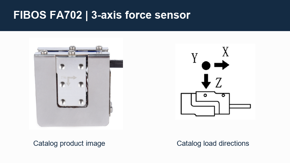
Choose a 3-axis force sensor when you need to separate a normal load from two lateral loads, such as when measuring a contact force on a test fixture. The FIBOS FA702 is a catalog example with X, Y, and Z force measurement and a side cable exit. Check the allowable moments on the mounting arrangement even if your data system only records forces.
FIBOS FA702 catalog image and load direction diagram for X, Y, and Z force measurement.
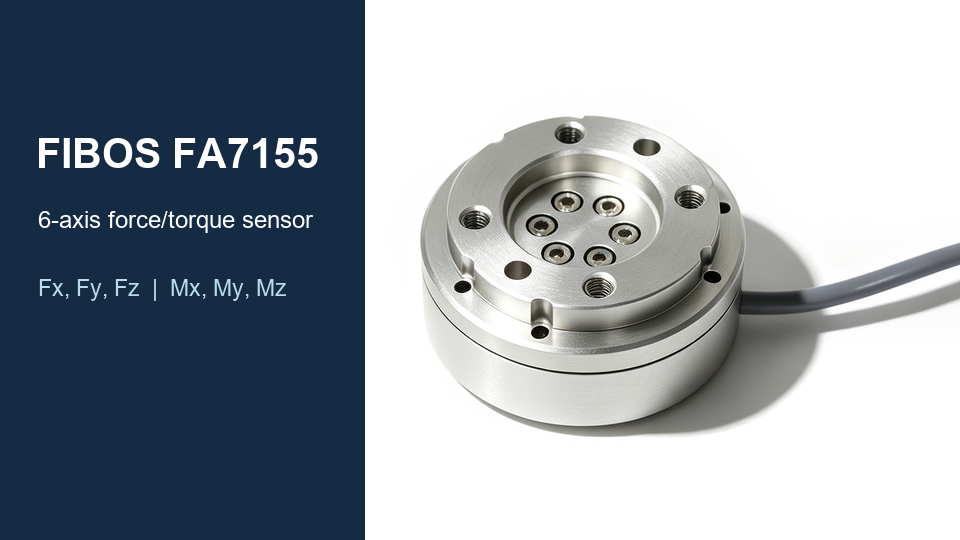
A 6-axis force/torque sensor measures three force and three moment components. On a robot wrist, those additional channels can help distinguish a straight push from a push that also bends or twists the tool. Check each component's calibrated range and the allowable combinations for the actual tool and motion.
FIBOS FA7155 Series six-axis force/torque sensor. Product photo from the FIBOS website.
· Axial Force and Torque Sensors: Fz and Mz
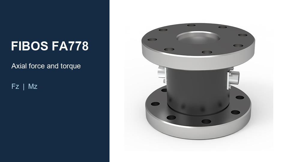
An axial force and torque sensor suits tests that need axial load and twist about the same line. The FIBOS FA778-5600 Series identifies these components as Fz and Mz in its catalog. For a push-and-twist test, confirm the direction and magnitude of each working load and check whether fixture misalignment adds side load or bending.
FIBOS FA778-5600 Series axial force and torque sensor. Product photo from the FIBOS website.
How Does a Strain Gauge Multi-Axis Force Sensor Work?
· How the Sensing Element Turns Loads into Electrical Signals
Applied loads deform the sensing element slightly. Strain gauges bonded to the element change resistance, and bridge circuits turn these changes into voltage signals. With a raw bridge output, sensitivity is often specified in mV/V, the signal per volt of excitation. The measurement electronics or software convert the signals into engineering units using the supplied calibration.
· What Causes Crosstalk, and How Does a Calibration Matrix Reduce It?
A load in one direction can produce a response in several raw channels because they share a sensing structure. Where the manufacturer supplies a calibration or compensation matrix, it combines the ordered input signals to estimate the individual loads. Compare residual crosstalk using the datasheet's test conditions and reference range. Keep the matrix, channel order, units, and applicable serial number together. HBK matrix compensation technical note
Where Are Multi-Axis Force Sensors Used?
· Robot End Effectors: Assembly, Polishing, and Contact Force Control
During insertion, lateral force or bending moment can help identify off-center contact. In polishing, the normal force can feed the control loop while lateral components help characterize contact. Include tool weight, tool orientation, and acceleration when estimating the loads the wrist sensor sees.
· Test Benches: Side Loads, Axial Loads, and Torque
A push-and-turn fixture can record axial load and torque together to compare test cycles. A fixture that also needs to capture side loads or bending moments calls for a sensor with those measurement channels. Define the force application point and verify that fixture supports do not carry part of the load around the sensor.
· Research Setups: Small Forces, Dynamic Loads, and Synchronized Measurements
For a small contact-force experiment, compare baseline noise and drift with the smallest effect you expect to observe. For transient tests, synchronize load channels with displacement or other instruments when timing matters. Verify the bandwidth of the assembled rig, since fixture compliance and resonance can influence the recorded waveform.
How Do You Size a Multi-Axis Force Sensor for Your Application?
· Estimate Working Loads, Peak Loads, and Moments from Tool Offsets
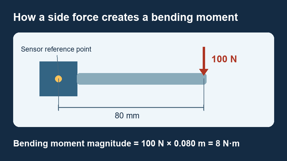
List the normal working loads and credible peaks in the sensor frame, including tool weight, acceleration, process forces, and transients as applicable. For example, a 100 N lateral force applied 80 mm along the tool axis from the sensor origin produces an 8 N·m bending moment when the force and offset are perpendicular. In general, the moment contribution is the offset vector crossed with the force vector. Add any applied couple and evaluate the signs for each operating case. ATI force/torque sensor selection guide
A 100 N side force perpendicular to an 80 mm offset produces an 8 N·m bending moment at the sensor reference point.
· Check Combined Loading Limits and Overload Ratings
Check the calibrated measuring range of each component and then use the manufacturer's combined loading diagram or calculation for simultaneous forces and moments. Individual ratings describe only part of the load case. An overload rating describes allowable loading under specified conditions and should not be used as a working measurement range. Include unmeasured side loads or moments in the mechanical check. HBK force/torque load analysis
· Compare Measurement Error and Resolution at Your Smallest Working Load
Convert percent-of-full-scale figures into force or moment units before comparing sensors. For example, a hypothetical error term of 0.2% of a 100 N full scale is 0.2 N, equal to 10% of a 2 N reading. That calculation covers one error term. Check noise, crosstalk from larger concurrent loads, repeatability, and temperature drift for the complete measurement chain.
What Should You Check Before Mounting and Connecting the Sensor?
· Mounting Dimensions, Load Path, and Sensor Orientation
Confirm bolt pattern, locating features, mounting faces, fastener requirements, and cable clearance against the drawing. Install the sensing element in the intended load path and check that guards, stops, or cables do not carry process load during normal operation. Document sensor orientation so the electrical channel map matches the mechanical setup.
· Excitation, Signal Conditioning, and DAQ or Controller Compatibility
For raw bridge outputs, confirm excitation, differential input range, channel count, shielding, and where calibration is applied. For conditioned or digital outputs, check supply, signal range or protocol, pinout, update rate, and units. Determine whether the sensor interface already reports compensated values before adding matrix processing in the PLC or DAQ.
How Do You Verify the Sensor After Installation?
· Confirm Channel Mapping, Polarity, Units, and Zero With the Tool Installed
Record the installed orientation and the unloaded baseline. If the tool's weight should be excluded from the displayed process load, tare in a defined pose and document that pose. A tare shifts the reported baseline while the sensor still carries the tool. On moving equipment, check how the gravity components change with orientation.
· Apply Known Loads to Check Axis Response and Crosstalk
Apply known loads in documented directions and at known positions. Check the expected sign and magnitude on the primary channel and the residual response on the others. For moment channels, use a known force and perpendicular lever arm or an appropriate reference torque. Repeat a representative combined loading case if the fixture can reproduce it. Record the setup and results for future troubleshooting or replacement.
Frequently Asked Questions
1. Can a 3-axis force sensor measure torque if I know the lever arm?
You can calculate the moment contribution of a measured force when its point of application is known. An independent couple, or a change in where the force acts, requires additional information or moment measurement.
2. Can I load every axis to its rated capacity at the same time?
Only if the manufacturer confirms that the specific combination is allowed. Check the combined load envelope for the intended calibration and include moments from adapters and tool offsets.
3. Can I report force and torque at the tool tip instead of the sensor origin?
Yes, when the required load components and the geometry between frames are known. For a six-component measurement, translating the reference point changes the reported moment by the corresponding force and lever-arm term. Rotating the frame also changes the reported components. ATI tool transformation manual
4. What should I check before replacing an existing multi-axis force sensor?
Match the measured components, axis signs and origin, mounting geometry, operating and overload limits, output, excitation or power, connector, and controller settings. Compare error and bandwidth in the actual use case, then repeat known-load and combined-load checks after installation.
5. Can I reuse the original calibration matrix with a replacement sensor?
Use the calibration supplied or approved for the replacement unit and its measurement chain. Confirm the serial number, channel order, scaling, and where the matrix is applied, then verify the outputs with known loads.