You are here:Home » Blog » Inline Tension & Compression Force Sensors: Types, Applications, and How to Choose
Inline Tension & Compression Force Sensors: Types, Applications, and How to Choose
Views: 0 Author: Site Editor Publish Time: 2026-11-06 Origin: Site
An inline tension and compression force sensor, also called an inline load cell or threaded tension–compression load cell, mounts in series between two components and measures the axial push and pull forces that pass through that joint. In a linear actuator, it sits between the rod and the tool. In a test stand, it sits between the moving crosshead and the specimen fixture. The reading is only as good as the load path: every newton you want to measure must pass through the sensor, and nothing else should carry load around it.
If you only have two minutes, these are the points that most often decide whether an inline load cell works as intended:
Trace the load path first. Any bracket, guard, or hard stop that touches the assembly during measurement becomes a parallel path and lowers the reading.
Size capacity from the physical load at the sensor, including preload and fixture weight, not from the value shown after zeroing.
Convert percent-of-full-scale errors into newtons at your smallest working force before comparing datasheets.
Match the thread at both ends, the installed length with adapters fitted, and the cable exit to the real envelope, ideally with the supplier's 3D model.
A raw mV/V bridge output needs excitation and a bridge input or amplifier; a standard PLC analog input cannot read it directly.
Verify both directions with the tooling installed. A tension-only certificate says nothing about compression accuracy.
What Is an Inline Load Cell, and How Does It Measure Push and Pull Forces?
· Axial Load Path: Tension and Compression Along the Same Axis
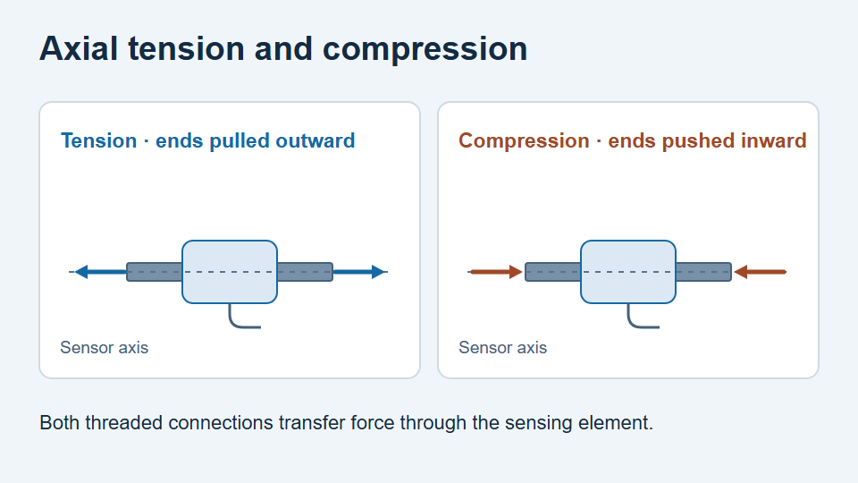
The two ends of an inline load cell transfer force through its sensing element. A tensile load pulls the ends apart. A compressive load pushes them together. To capture the intended force, place the sensor between the moving member and the part of the assembly whose load you need to measure. A support or bracket that carries some of that force around the sensor changes the reading.
Figure 1. Tension and compression act along the same axis, in opposite directions. Conceptual diagram.
· How a Strain Gauge Load Cell Converts Force into an mV/V Signal
In a strain gauge design, the elastic element deforms slightly under load. The gauges change resistance, and an excited Wheatstone bridge produces a small differential voltage. The sensitivity on the datasheet is commonly given in millivolts per volt of excitation (mV/V). As an illustration, 1.5 mV/V at 5 V excitation gives 7.5 mV of signal change at rated load in the specified direction. The calibration relates bridge output to force in newtons. The NI bridge-based load measurement guide supports instrument selection.
Which Inline Load Cell Design Fits Your Assembly?
· External Threaded Studs vs. Internal Threaded Connections
External studs mate with threaded couplers or tooling. Internal threads accept a mating stud or adapter. Some models use different end connections. Check both ends of the drawing for thread depth, shoulder clearance, and any specified loading or clamping surfaces.
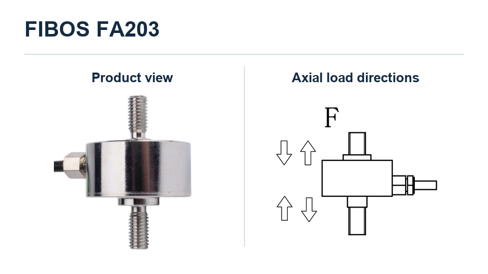
As a reference for what a product page should tell you, the FIBOS FA203 inline force sensor is listed with capacities from 50 N to 2,000 N, a φ25.4 mm × 37 mm stainless steel body, a nominal sensitivity of 2.0 mV/V, a safe overload of 150% F.S., and a recommended excitation of 5–12 V. Its mounting drawing distinguishes thread sizes by capacity group, so download the drawing for the exact capacity under consideration rather than assuming one thread for the whole series. Across the FIBOS rod end force sensor range, inline models are listed with M4, M8, and M12 thread options among others, which makes thread size a product-family decision rather than an afterthought.
· Miniature Inline Load Cells for Tight Mounting Clearances
For compact actuators or small laboratory fixtures, check the complete installed envelope. Couplers and locknuts add length, and the cable exit needs room for routing and strain relief. Include space for a wrench and check clearance at both ends of the stroke. For example, the FIBOS FA201 miniature inline load cell is listed at φ13 mm × 31 mm with capacities from 50 N to 1,000 N and M4 threads; at that size, a coupler and locknut can add a significant share of the installed length. Confirm the rated loading direction and calibration scope for the capacity you select before specifying push–pull duty. FUTEK's inline load cell series illustrates how body size and thread options vary within a single product family.
· Inline vs. S-Beam and Donut Load Cells: How the Load Path Differs
A compact threaded inline design suits a rod-to-tool or rod-to-fixture connection. An S-beam load cell can also sit in series and measure push and pull when its mounting and directional ratings support both. It has a different body envelope and may suit a test frame with more room around the load axis. A through-hole or donut force sensor suits assemblies where a bolt or shaft passes through the sensor and transfers load through the specified faces. Compare how each design actually carries force in your assembly. For a broader comparison of sensing principles and body styles, see the FIBOS force sensor guide.
The table below summarizes the practical differences. FIBOS lists S type force sensors and donut force sensors as separate categories for the same reason: the mounting geometry, not the sensing principle, usually decides which one fits.
Design
Typical mounting
Where it fits best
Watch out for
Threaded inline load cell
Threaded studs or internal threads in series with a rod or coupler
Installed length with adapters; side loads from misalignment; torsion during tightening
S-beam load cell
Threaded holes at top and bottom of an S-shaped body
Test frames and hanging or suspended loads with room around the load axis
Larger envelope; off-axis sensitivity; check that the model is rated for both directions
Through-hole or donut load cell
Ring clamped in a stack; bolt or shaft passes through the bore
Bolt preload, clamping stacks, assemblies where the shaft must pass through the sensor
Mostly compression-rated; loading and support faces are defined by the drawing
Where Are Inline Tension and Compression Force Sensors Used?
· Linear Actuator Force Feedback
An inline load cell between a linear actuator rod and a tool measures the axial force transmitted at that point. A controller can use the signal to detect contact or regulate force. During rapid moves, the reading can include the force needed to accelerate downstream tooling. Check this effect when the aim is to estimate contact force at the workpiece.
Figure 2. The FIBOS FA203 product image and load direction diagram from the product manual show the two threaded ends and axial loading in tension and compression.
· Press-Fit Assembly and Insertion–Extraction Force Testing
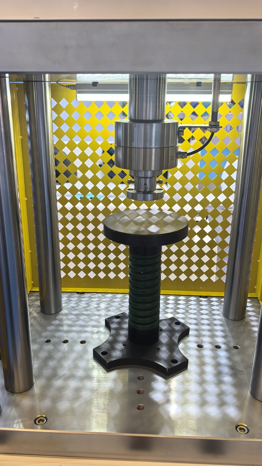
A press-fit station can record compressive force against tool displacement to check how a part seats. An insertion–extraction fixture can record the insertion peak and the pull-out peak in one setup if its tooling transfers both loads through the sensor. Synchronize force and displacement so each peak can be tied to a position or a stage of the cycle. Automotive press-fitting, automated assembly, and 3C component testing are typical duties listed for compact inline models such as the FA203.
Figure 3. In this press station, the vertical press head is centered above the round fixture that supports the part.
· Push–Pull Testing in Lab Fixtures and Test Stands
On a research test stand, an inline load cell can track force as a specimen or mechanism is loaded and unloaded. For low-force work, check the noise and repeatability with the actual grips fitted. During reversals, inspect the grips and couplers for play. Mechanical backlash can produce a flat segment in a force–displacement curve before the opposite load starts to build.
How Do You Choose the Right Inline Load Cell?
· Match Thread Size, Pitch, Engagement Length, and Installed Length
Specify the thread standard, diameter, pitch, and usable engagement at both ends. On a blind hole, verify that the adapter seats as intended before it reaches the bottom. Confirm the distance between mounting interfaces after adapters are fitted. That dimension determines whether the tool reaches the workpiece and clears surrounding parts over the full stroke. Where a supplier offers 3D model files, as FIBOS does for its inline sensors, drop the model into the assembly before ordering instead of checking the envelope on paper.
· Size the Load Cell for Working Forces, Peak Loads, and Overload
List normal and peak physical loads separately for tension and compression. Include fixture weight where it acts through the sensor, assembly preload, and credible transients such as a hard contact. For example, a 150 N compressive preload followed by an additional 400 N in compression gives about 550 N of physical load before any impact or side load. Select a rated range that covers the expected working peaks with a margin suited to the application. Treat the safe-overload rating as a separate limit and check permissible side loads, bending moments, and torsion. A 150% F.S. safe overload, as listed for the FA203 and FA201, is a survival limit under the stated conditions, not an extra calibrated working range.
· Check Accuracy and Resolution at the Smallest Force You Need to Measure
Convert percent-of-full-scale specifications to force units. A single error term of 0.1% of full scale on a 2,000 N load cell corresponds to 2 N. At a 10 N working force, that one term alone is equivalent to 20% of the reading. Treat this as a screening calculation. Evaluate other applicable errors, zero drift, hysteresis during reversal, and the noise of the installed measurement chain. Verify that repeated measurements can distinguish the smallest change that matters to the process.
· Check System Bandwidth and Fatigue Ratings for Repeated Push–Pull Cycles
Use the fastest feature that matters, such as a short insertion peak, to specify the required response. Tooling mass and fixture stiffness affect the installed system's resonance. The usable bandwidth also depends on the amplifier, filtering, and acquisition settings; a natural frequency above 5 kHz on a datasheet does not mean the installed chain can resolve a 5 kHz event. For repeated load reversals, ask for fatigue data that matches the load amplitude, mean load, and cycle count. Check the operating temperature, protection rating, and cable routing against actual exposure and motion.
· Inline Load Cell Selection Checklist
Before requesting a quotation or a sample, work through the checks below. Each row pairs the parameter to confirm with the mistake that most often causes a mismatch between the datasheet and the installed result.
Parameter
What to confirm
Common mistake
Thread and end connections
Standard, diameter, pitch, engagement length, internal or external at each end
Assuming one thread size applies to every capacity in the series
Installed length
Face-to-face distance with couplers, locknuts, and rod-end bearings fitted
Reading only the body height from the datasheet
Capacity
Preload plus working force plus credible peaks, separately for tension and compression
Sizing for the force shown after zeroing
Rated directions
Tension, compression, or both, with the accuracy stated for each
Assuming a threaded sensor is automatically bidirectional
Accuracy basis
Each error term converted to newtons at the smallest force that matters
Reading %F.S. as a percentage of the reading
Side load and moment limits
Permissible off-axis force, bending moment, and torsion
Checking axial capacity only
Signal chain
mV/V output, excitation range, bridge resistance, and the amplifier or module input
Wiring the bridge output directly to a standard PLC analog input
Dynamics and fatigue
Fastest force feature, installed resonance, cycle count, and load amplitude
Treating datasheet natural frequency as usable bandwidth
Environment
Compensated and operating temperature ranges, IP rating, cable flexing and routing
Treating an IP rating as chemical or coolant resistance
Calibration scope
Directions, points, uncertainty, and acceptance limits to be stated on the certificate
Accepting a single-direction certificate for push–pull duty
How Do You Install an Inline Load Cell and Avoid Side Loads?
· Keep the Load Axial Throughout the Actuator Stroke
Align the actuator, load cell, and tool at the operating positions where force will be measured. Check for guide misalignment, fixture deflection, and cable pull at both travel limits. At a safe, low force, compare the response at several stroke positions using a repeatable reference load. A position-dependent discrepancy can reveal changing alignment or a fixture contact.
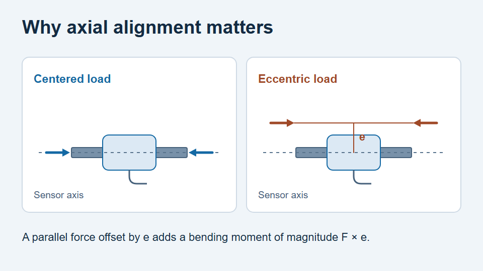
Figure 4. An offset force line adds a bending moment. Check alignment throughout the stroke. Conceptual diagram.
· Minimize Side Loads, Bending Moments, and Torsion During Tightening
A 500 N force whose line of action is offset by 2 mm produces a bending moment of 1 N·m at the sensor. The effect on the reading depends on the sensor and mount. Keep force introduction centered and check the manufacturer's combined load limits. During assembly, follow the model's tightening sequence and torque limits, and use the specified wrench flats or counterhold points. The FUTEK LCM mounting manual gives model-family examples of installation torque and off-axis loading checks.
· Check for Fixture Interference and Alternate Load Paths
Check that an adapter, nut, guard, or hard stop does not touch a surface that should remain clear during measurement. Such contact can create a parallel load path, known as a force shunt. The display may then show only the portion of the applied force passing through the load cell. Inspect both directions and the full travel range because a gap can close only under a particular load or position.
How Do You Connect an Inline Load Cell to a PLC or DAQ?
· Match Bridge Excitation, mV/V Output, and Signal Conditioning
A passive bridge load cell needs a compatible excitation source and a differential bridge input. Check the excitation range, bridge resistance, wire functions, and input range in the sensor and instrument documents. Use a bridge input module or a compatible load cell amplifier when the PLC has only standard voltage or current inputs. Where an amplifier maps bidirectional force to a unipolar output such as 4–20 mA, reserve signal range on both sides of the chosen zero-force output and verify the mapping.
· Verify Signal Polarity, Input Range, and Sampling Rate
Apply a known push and pull and verify the sign at the PLC or data acquisition system (DAQ). Confirm that neither end of the required force range clips at the amplifier or input module. Set sampling and anti-alias filtering for the fastest feature to be measured. If the PLC scan or communications update is too slow to retain a peak, capture it with suitable high-speed acquisition and send the result to the PLC.
How Do You Calibrate and Verify an Inline Load Cell?
· Check Zero and Repeatability After Mounting
Record the mounted reading at a defined reference condition before taring. Repeat several load and unload cycles and record how closely the reading returns to the reference. Investigate a significant change after tightening or after force reversal. Check for mechanical preload, loose joints, binding, and an unstable electrical zero before deciding whether to retare or adjust the assembly.
· Verify Both Directions with Known Tension and Compression Loads
Use a suitable reference, such as a calibrated reference load cell mounted in series, to apply or measure known forces in both directions. Check several points across the working range, including the lowest critical force, and record readings on loading and unloading. Compare the final value in newtons at the PLC or DAQ with the reference. If accuracy or traceability is contractual, specify the calibration directions, points, uncertainty, and acceptance limits when ordering or scheduling calibration. For fast events, separately verify that the installed measurement chain preserves the required peaks and timing.
Replacing an Existing Inline Load Cell: What to Compare Beyond Threads and Capacity
Many inline load cells are bought to replace a unit that failed, was overloaded, or is no longer available. Matching threads and capacity is the first screen, not the whole job. The table below lists what to collect from the old installation and what to compare on the candidate's datasheet and drawing. If the original drawing is unavailable, measure the installed length between mounting faces, photograph the cable exit and wrench flats, and read the existing amplifier's excitation and input range before shortlisting a replacement.
Item
Collect from the old installation
Compare on the candidate
Mechanical fit
Thread size and type at each end, installed length, wrench flats, cable exit direction
Drawing for the matching capacity group; adapters needed to reach the same length
Force ratings
Rated capacity, actual working and peak loads seen in service, overload history
Rated load and safe overload in each direction; side load and moment limits
Electrical interface
mV/V sensitivity, bridge resistance, wiring colours and functions, excitation in use
Sensitivity and bridge resistance the existing amplifier can accept without rescaling, or the new scaling required
Dynamics
Cycle rate, fastest peak captured, filter settings in the controller
Stiffness, natural frequency, and fatigue data for the same duty
Environment
Temperature, coolant or dust exposure, cable movement
Compensated temperature range, IP rating, cable specification
Acceptance
How the old sensor was zeroed and verified in the machine
Two-direction verification with the replacement fitted before releasing the machine
When no catalog model matches the installed length, thread combination, or cable exit, ask whether a modified version is available before redesigning the fixture. FIBOS lists non-standard customised sensors for this situation; send the old drawing or the measured dimensions together with the force range and the amplifier details so that the proposal covers the whole measurement chain, not only the sensor body.
Frequently Asked Questions About Inline Load Cells
1. Are Tension and Compression Ratings Always the Same?
They can differ by model or configuration. Check the rated load, safe-overload limit, and specified accuracy in each direction. Also check the ratings of the adapters and any other parts in the load path.
2. Is a Tension-Only Calibration Enough for Push–Pull Testing?
If both force readings need a stated accuracy, calibrate or verify both directions as required by the application. A tension-only certificate establishes results for tension. Some bidirectional models offer calibration in the second direction separately, so confirm the scope of the certificate when ordering.
3. Can a Rod-End Bearing Help Reduce Misalignment?
A suitable spherical rod-end bearing can accommodate some angular misalignment. Check allowable articulation, clearance, backlash, and push–pull ratings. Bearing play and friction can affect small-force measurements and readings during reversals. A catalog label such as “rod end” may describe the sensor's threaded mounting style, so check whether a bearing is actually included.
4. Does Zeroing the Load Cell Remove Mechanical Preload?
Zeroing changes the displayed reference. The mechanical preload still acts on the load cell and must be included when checking capacity, overload, and fatigue conditions. Record the physical preload or document the reference condition used for taring.
5. What Information Should I Send to Get a Usable Quotation for an Inline Load Cell?
Send the working and peak forces in each direction, the thread size and type at both ends, the maximum installed length, the cable exit and length, the excitation and input range of the amplifier or PLC module, the operating temperature and protection requirement, and whether a two-direction calibration certificate is needed. A drawing or photo of the mounting location saves at least one round of questions. The FIBOS contact page accepts these details directly.