You are here:Home » Blog » Load Cells: Types, Applications, and How to Choose
Load Cells: Types, Applications, and How to Choose
Views: 0 Author: Site Editor Publish Time: 2026-11-09 Origin: Site
A load cell converts an applied force into a measurable signal. In a scale, an indicator uses that signal to calculate the weight reading. In a press or test stand, the same measurement principle can track force in newtons. Start with the load path: identify what the sensor will support, which direction the force will act, and the smallest change the system needs to detect. Those three answers narrow down the mounting style, rated capacity, and electronics.
What Is a Load Cell, and What Does It Measure?
· How Scales Use Force Measurements to Determine Weight
A load cell measures the force transmitted through its sensing element. A stationary scale uses calibration to relate the force from gravity to a displayed mass, commonly in kilograms. If a pipe, a stop, or another support carries part of the load, the reading can change even when the mass on the scale stays the same. Taring removes the empty platform or vessel from the displayed value while its weight still acts on the sensors.
· Tension, Compression, and Bidirectional Force Measurement
A suspended load pulls on a sensor in tension. A platform or press typically pushes on a sensor in compression. For an actuator that both pushes and pulls, check the model's ratings and calibration data in both directions, including how the fixture transmits force as it crosses zero.
How Does a Load Cell Work?
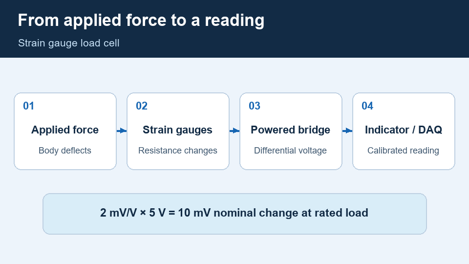
In a strain gauge load cell, the applied force slightly deforms an elastic body. Strain gauges on the body change resistance, and a powered Wheatstone bridge converts that change into a small voltage. The indicator or acquisition system uses calibration data to turn the voltage into a force or weight reading.
For example, a load cell rated at 2 mV/V produces a nominal 10 mV signal change from zero load to rated load with 5 V excitation. Use the actual rated sensitivity and permitted excitation when choosing the instrument input range.
An applied load changes bridge output. The calibrated instrument converts that signal into a force or weighing reading.
What Are the Main Types of Load Cells?
The eight groups below follow the FIBOS product range. Compare how each body mounts and how force enters it. The model drawing and rated load direction determine whether a particular sensor fits your assembly.
· Single Point Load Cells
A single point load cell can support a platform on one sensor. Within the specified platform size, the design compensates for loads placed away from the center. Check the maximum platform dimensions and the fixed and loaded ends on the drawing before designing the base.
· Shear & Cantilever Beam Load Cells
A single-ended beam is fixed at one end and loaded toward the other. A shear beam senses shear strain in its designed sensing region. For a floor scale or a weighing frame, check the required loading foot or mount and the clearance that lets the loaded end deflect. The mounting drawing identifies how the beam is supported and loaded.
· Bending Beam Load Cells
A bending beam measures strain caused by bending under load. For a compact weighing assembly, check the specified force application point, mounting clearance, and sealing. If the sensor has a protective bellows, use the mounting drawing to locate the load point and keep fixtures clear of the bellows.
· S-Beam Load Cells
An S-beam load cell typically takes force through threaded connections at both ends. It can suit suspended weighing or push-pull testing when rated for the required directions. Check thread size, installed length, and whether the end fittings can keep the load aligned through the full travel.
· Spoke & Pancake Load Cells
Spoke and pancake load cells offer a low-profile format for setups such as presses and test frames. Check how the center loading interface and outer mounting area work together. A fixture that contacts both can create a parallel load path and reduce the force measured by the cell.
· Tension Link & Crane Load Cells
A tension link sits in the suspended load path, commonly between shackles or other compatible fittings. Check the fitting dimensions and the working load limit of the complete assembly for the intended use, including lift dynamics. Follow the equipment manufacturer's instructions for rigging and installation.
· High-Capacity Column Load Cells
A high-capacity column load cell is an option when a large load can be directed along the sensing axis. A rocker-column design may be used in a weighing assembly with its specified seating hardware. Check the contact surfaces, centering arrangement, and allowable movement rather than choosing by capacity alone.
· Load Pin Load Cells
A load pin measures force at a joint such as a clevis or sheave. The pin is part of the load-bearing assembly. Check pin diameter, support spacing, sensing direction, and the features that prevent axial movement and rotation. Confirm the indicated load against the assembly geometry, particularly when the pin measures a sheave reaction.
Which Load Cell Type Fits Your Application?
· Platform Scales and Checkweighers
For a compact platform, compare single point cells by platform size and the smallest product weight change the scale must detect. A large platform may use several beam cells. On a conveyor checkweigher, verify the reading at the intended belt speed and product spacing as well as with stationary loads.
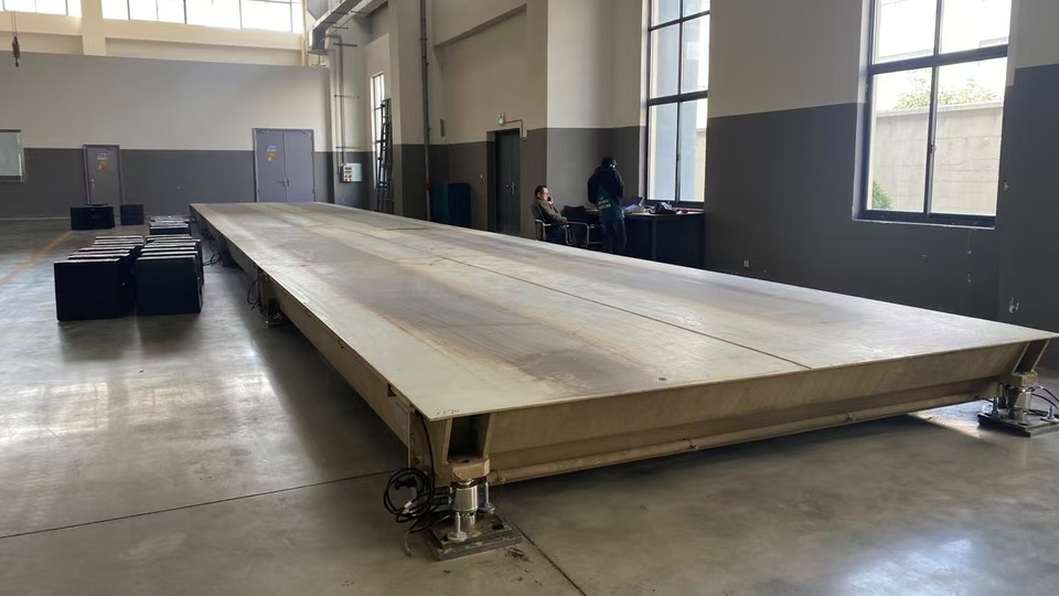
Industrial platform scale. Verify how the deck transfers load to each support before selecting sensor capacity.
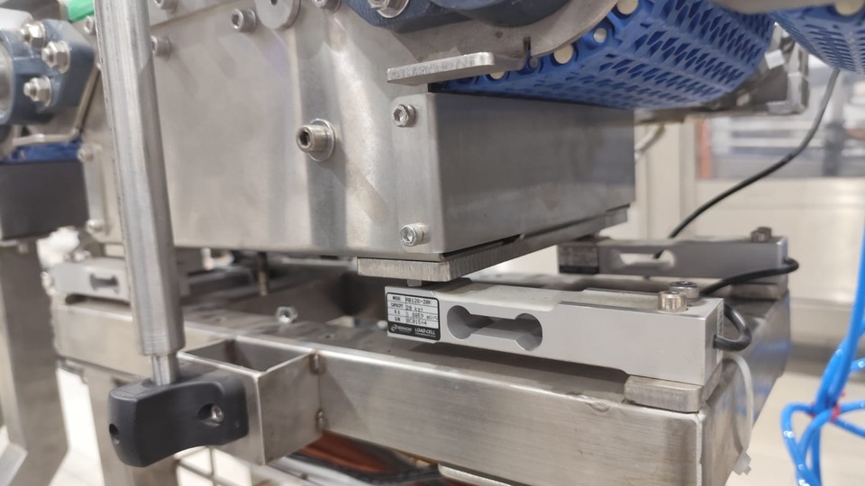
Checkweigher assembly. Verify the weighing result at the intended belt speed and product spacing.
· Tank, Hopper, and Silo Weighing
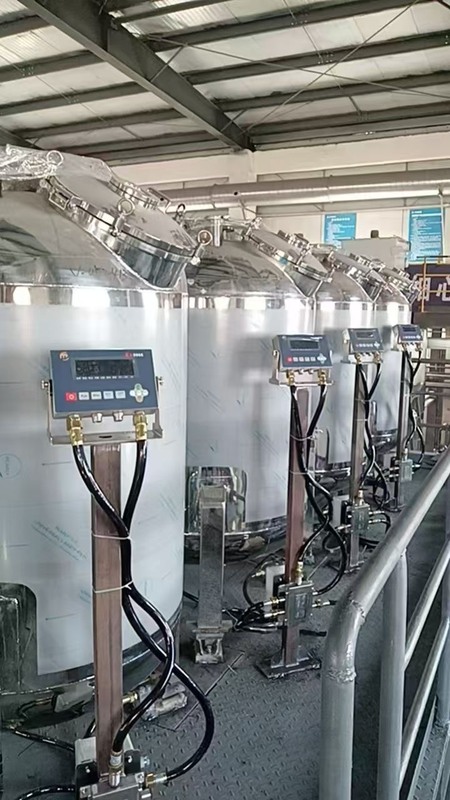
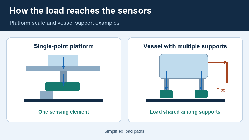
For a vessel supported on legs, calculate the load at each support. A weighing module combines a load cell with mounting hardware selected for the vessel arrangement. Review piping connections, thermal movement, and any lateral or uplift restraint the installation requires. Rigid piping can carry part of the vessel load and distort the weight reading.
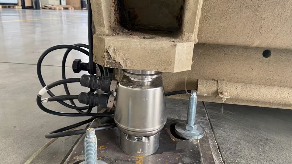
A vessel support and its weighing assembly. Check the entire load path, including external restraints and piping.
Vessel installation overview. Include piping connections when checking how each vessel transfers load to its supports.
· Suspended Weighing and Crane Load Monitoring
Use the location of the force measurement to narrow the choice. A tension link measures force along a suspended connection. A load pin measures force at a joint. On a pulley assembly, check the relationship between pin reaction and line tension for the actual rope routing.
Port crane installation. The measurement location depends on the lifting assembly and its load path.
· Press Force Monitoring and Test Stand Measurements
For a press with limited stack height, compare low-profile cells by mounting height and fixture stiffness. For push-pull testing, check the sensor and fixture in both directions. If a short peak force matters, verify the response of the complete measurement chain, including the sample rate and any filtering.
How Do You Choose the Right Load Cell?
· Size Capacity for Dead Load, Working Load, and Peak Loads
List what each sensor carries before production starts, during normal operation, and at the highest expected load. Include the platform or vessel, fixtures, contents, and foreseeable force peaks. Compare the maximum operating load with rated capacity. Check safe overload separately against the datasheet's definition and loading conditions.
· Account for Uneven Load Sharing in Multi-Cell Systems
A four-cell platform with a 1,200 kg gross load would average a 300 kg load equivalent per cell if sharing were equal. If an off-center load puts 40% of the total on one support, that cell already sees the equivalent of 480 kg before any additional transient loads. This is an illustrative calculation. Use the worst support reaction for your actual geometry, loading positions, and operating conditions.
· Evaluate Measurement Error at the Smallest Load You Need to Measure
Compare errors in the same unit as the measurement. For example, a nonlinearity specification of 0.05% of full scale on a 1,000 N cell corresponds to 0.5 N. At a 10 N working point, that amount is 5% of the reading. It represents one specified error component. Also evaluate hysteresis, repeatability, temperature effects, and electronics noise under the conditions that matter to your process.
· Check Mounting Dimensions, Temperature Range, and Ingress Protection
Use the dimensional drawing to check bolt patterns, loading height, and cable exit space. Compare the operating and compensated temperature ranges with the conditions at the sensor. For washdown or outdoor equipment, check the rating of the complete connection, including the cable entry, connector, or junction box.
How Do You Install and Wire a Load Cell?
· Check the Load Path, Alignment, and Mounting Surfaces
Trace the force from the object through the load cell to its support. Check that loading surfaces and fasteners match the drawing and that the assembly remains aligned throughout its travel. Inspect piping, cables, guards, and stops for contact or restraint that could divert force or add side load.
The platform carries load through one sensor in this example. A vessel distributes its load across supports, and rigid piping can divert part of it.
· Match 4-Wire or 6-Wire Connections to the Indicator or Amplifier
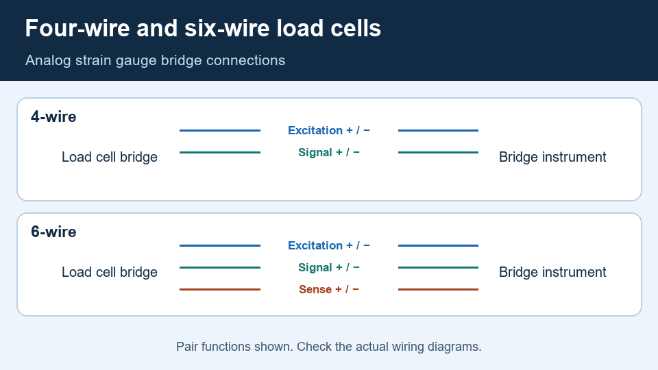
A four-wire bridge connection has two excitation leads and two signal leads. A six-wire connection adds two sense leads so a compatible instrument can account for voltage drop in the excitation wiring. Identify terminals by function using both wiring diagrams. Follow the instrument manual for sense terminals and shielding, since wire colors and terminal arrangements vary.
Four-wire and six-wire bridge connections by function. Verify terminals and shield connections in the sensor and instrument diagrams.
· Connect the Load Cell Signal to a PLC or DAQ
Use a bridge-capable input module or a signal conditioner that accepts the cell's mV/V output and provides the required excitation. If the PLC expects a standard signal such as 4–20 mA, use a compatible transmitter. Before commissioning, confirm polarity, engineering units, usable input range, and the acquisition rate required by the process.
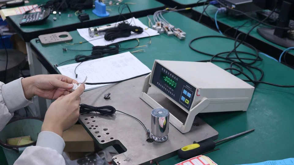
FIBOS electrical test bench. Confirm the signal at the instrument before verifying the reading at the control or acquisition system.
How Do You Calibrate and Verify a Load Cell After Installation?
· Check Zero and Calibrate Span with Known Loads
With the assembly in its defined empty or unloaded condition, record the zero reading. Apply reference weights for a scale or a known reference force for a test stand. Set the span as specified by the instrument procedure, then verify the displayed values at points across the working range. For bidirectional measurement, verify both directions if both are used.
· Verify Repeatability and Check Corner-Load Error on Platform Scales
Apply and remove the same reference load several times to check repeatability and return to zero. On a platform scale, move the reference load to the specified test positions and compare the readings. If position changes the result, inspect the load path and support conditions, then follow the scale procedure for any required corner adjustment and re-verification.
What Should You Check Before Replacing a Load Cell?
· Compare Capacity, Load Direction, and Mounting Dimensions
Start with the original model and drawing. Compare capacity, allowable load directions, mounting dimensions, installed height, and loading interfaces. Check the minimum useful measurement, overload requirements, and environmental conditions against the replacement datasheet. A change in installed height or loading geometry can change how a multi-cell system shares the load.
· Confirm Wiring and Signal Compatibility, Then Recalibrate the System
Compare sensitivity, excitation, wiring functions, and any digital protocol with the existing indicator or controller. In an analog multi-cell system, also check whether the junction box and indicator support the new cell's electrical characteristics and any required adjustment. After installation, recalibrate and verify zero, span, and applicable load-position checks before accepting the replacement.
Frequently Asked Questions About Load Cells
1. What Is the Difference Between a Load Cell and a Strain Gauge?
A strain gauge senses local deformation. A strain gauge load cell combines gauges with a designed elastic body and a bridge circuit so the assembly can be calibrated to measure a defined force.
2. What Is the Difference Between a Load Cell and a Weighing Module?
The load cell is the sensing element. A weighing module includes the sensor and mounting hardware that introduces the load and manages movement or restraint as specified for that assembly.
3. Does a Higher-Capacity Load Cell Make a Scale More Accurate?
A larger capacity provides more room for load, but a small weight change uses less of the available signal range when sensitivity and excitation are comparable. Compare the expected system error and resolution at the smallest weight change you need to detect.
4. Why Does a Load Cell Reading Drift Under a Constant Load?
Possible causes include sensor creep, temperature change, and gradual movement or settling in the mounting assembly. Record how the reading changes under a stable reference load and compare it with the unloaded zero over time. Check whether the change tracks temperature or occurs mainly after loading.
5. Can You Replace Just One Load Cell in a Multi-Cell Weighing System?
Yes, if the system supports an individually compatible replacement. Verify mechanical fit and electrical compatibility first. After fitting the cell, check load sharing or corner response as applicable, then recalibrate and verify the complete scale.