You are here:Home » Blog » Force Sensors: Types, Applications, and How to Choose
Force Sensors: Types, Applications, and How to Choose
Views: 0 Author: Site Editor Publish Time: 2026-11-04 Origin: Site
A force sensor converts an applied mechanical force into a measurable electrical signal. To choose one, first define the loading direction, expected force range, installation space, and measurement speed. Then match the sensing principle and output to the complete measurement system. A sensor that fits mechanically still needs a suitable load path, signal conditioner, and calibration to produce useful results.
This guide focuses on four practical designs: miniature and button, through-hole and donut, inline tension and compression, and column force sensors. It also explains when a load cell, multi-axis sensor, or dedicated tension sensor may better suit the task. The aim is to help equipment engineers and research teams turn a measurement requirement into a testable sensor specification.
Inside the FIBOS workshop: assembly workstations, equipment, and carts holding sensor components.
What Is a Force Sensor, and What Does It Measure?
· Tension and Compression Force Measurement
A force sensor measures a mechanical load transmitted through its sensing structure. Compression pushes its loading interfaces toward each other; tension pulls them apart. Force is commonly expressed in newtons (N) or kilonewtons (kN). The measurement axis and positive signal direction should be defined before the sensor is installed.
A compression-only button sensor does not become a tension sensor when its signal polarity is reversed. Bidirectional measurement requires a mechanical connection that transmits both pulling and pushing loads, together with a suitable sensor specification and calibration for the required directions.
· Force Sensors, Load Cells, and Pressure Sensors: How Do They Differ?
Force sensor, force transducer, and load cell are overlapping industry terms. A load cell can measure force in an assembly machine as well as support a weighing platform. Product families help organize a catalog, but the loading geometry, measurement direction, and performance determine whether a particular device fits the application.
A fluid pressure sensor measures pressure, usually in pascals, kilopascals, or bar, through a pressure port or diaphragm. A contact force sensor measures the resultant force through its loading interface. Dividing force by a defined area gives average pressure only when the area and loading assumptions are valid; it does not reveal how pressure is distributed across the surface.
· When Should You Consider a Load Cell, Multi-Axis Sensor, or Tension Sensor?
Consider an S-beam, spoke or pancake, or load pin design when its mechanical load path better matches the machine. Choose a multi-axis sensor when separate force components or moments must be resolved. Web and wire tension measurement may need a dedicated tension sensor because roller geometry and material wrap angle affect the relationship between material tension and the force reaching the sensor.
In the FIBOS product organization, these are separate families or related load cell designs. This article uses Force Sensors for the four designs discussed below; that organization does not mean other load cells cannot measure force.
How Does a Force Sensor Work?
· Strain Gauge Force Sensors: From Deformation to an Electrical Signal
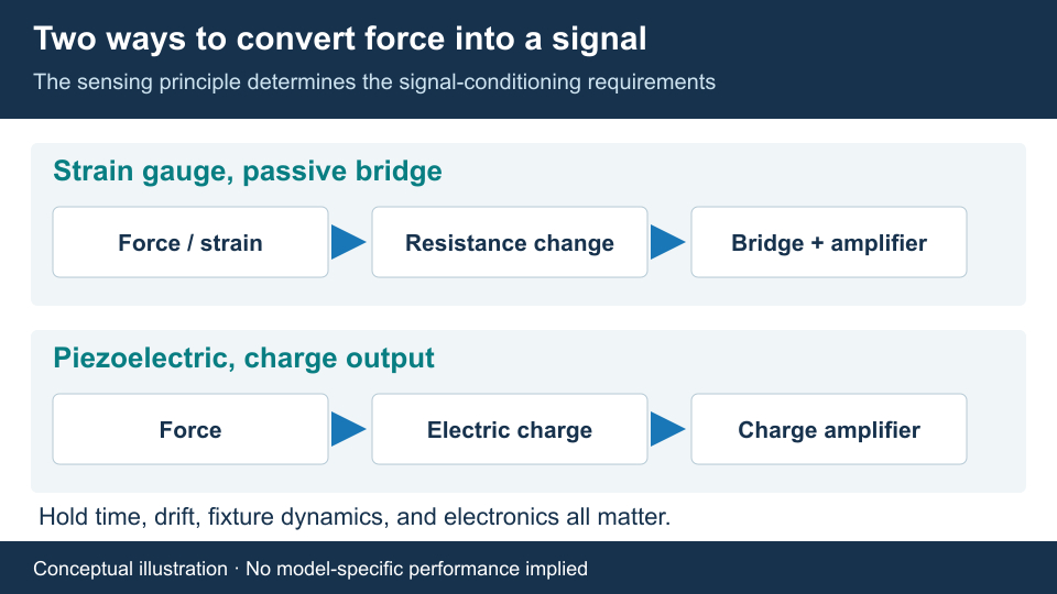
In a strain gauge force sensor, an elastic element deforms slightly under load. Bonded strain gauges change electrical resistance as that element strains. A bridge circuit converts the resistance changes into a small differential voltage when an excitation voltage is supplied. Calibration relates that output to applied force.
For a passive bridge sensor, sensitivity is often specified in mV/V. As an illustrative calculation, a sensor rated at 2 mV/V produces approximately 10 mV at rated load with 5 V excitation, after accounting for its zero offset. This is a general example, not a specification shared by all FIBOS models. The strain gauge and bridge principle is also described in FUTEK’s force measurement guide.
A technician working on a sensor assembly at a FIBOS workbench.
· Piezoelectric Force Sensors: From Applied Force to Electric Charge
A piezoelectric force sensor generates electric charge when its sensing material is loaded. Charge-mode sensors need suitable charge amplification, insulation, and low-noise cabling. Their small deformation and high stiffness can be useful for rapidly changing loads. Charge leakage and electronic drift must be considered when a load is held. Kistler’s comparison of piezoelectric and strain gauge sensors explains this tradeoff.
· Static, Quasi-Static, and Dynamic Measurement: Which Principle Fits?
Long hold-time measurements generally favor a strain gauge measurement chain with suitable creep and temperature performance. Strain gauge sensors also measure changing forces when their installed mechanical response and electronics are fast enough. Piezoelectric systems are useful for dynamic events and can support quasi-static measurements over a suitable time window. There is no universal hold-time limit that applies to every piezoelectric system.
Conceptual comparison of strain gauge and charge-output piezoelectric measurement chains. Principle, hold time, and electronics must be evaluated together.
Which Force Sensor Design Fits Your Application?
· Miniature & Button Force Sensors
A miniature or button force sensor is a candidate for compression measurement where axial height or diameter is limited. Typical integration questions concern the loading button, supporting surface, cable exit, and clearance around the body. A small package does not establish its minimum measurable force; noise, sensitivity, drift, and the installed fixture remain important.
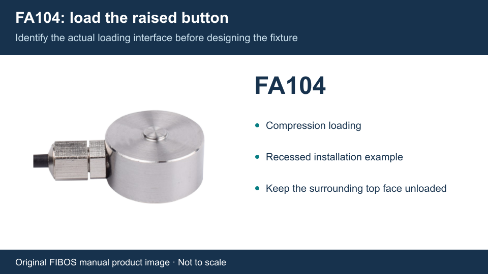
The FIBOS FA104 manual identifies the raised button as the force application point and states that the surrounding upper surface must not be loaded. Its recessed installation example helps explain why an upper platen must contact the button without bridging onto the surrounding structure. Browse miniature and button force sensors when evaluating this arrangement.
FIBOS FA104 product image reproduced from its manual. The manual identifies the raised button as the loading point; the surrounding top face must remain unloaded. Not to scale.
· Through-Hole & Donut Force Sensors
Through-hole and donut designs provide a central opening for integration around a bolt, shaft, or other machine feature, subject to the model drawing. Check the opening diameter, permitted contact annulus, supporting face, and available space for the cable. A central hole is a geometric feature; it does not by itself establish how the sensor should be preloaded or which force directions it can measure.
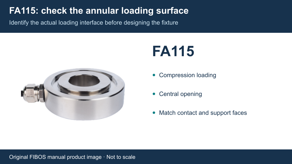
The FIBOS FA115 manual shows compression loading through a defined annular surface in a central-bolt assembly. The force read by the sensor depends on the installed load path; bolt tightening torque alone does not establish the measured force. Compare through-hole and donut force sensors against the intended contact and support geometry.
FIBOS FA115 product image reproduced from its manual. Its installation drawing defines the annular loading surface in a central-bolt arrangement. Not to scale.
· Inline Tension & Compression Force Sensors
An inline design places the sensing element in an axial connection between two parts. It is useful when a linkage or actuator must transmit both push and pull forces. Confirm thread size, engagement length, fixture alignment, and the load direction throughout the stroke. Prevent assembly torque from being reacted through a sensitive element unless the model instructions permit it.
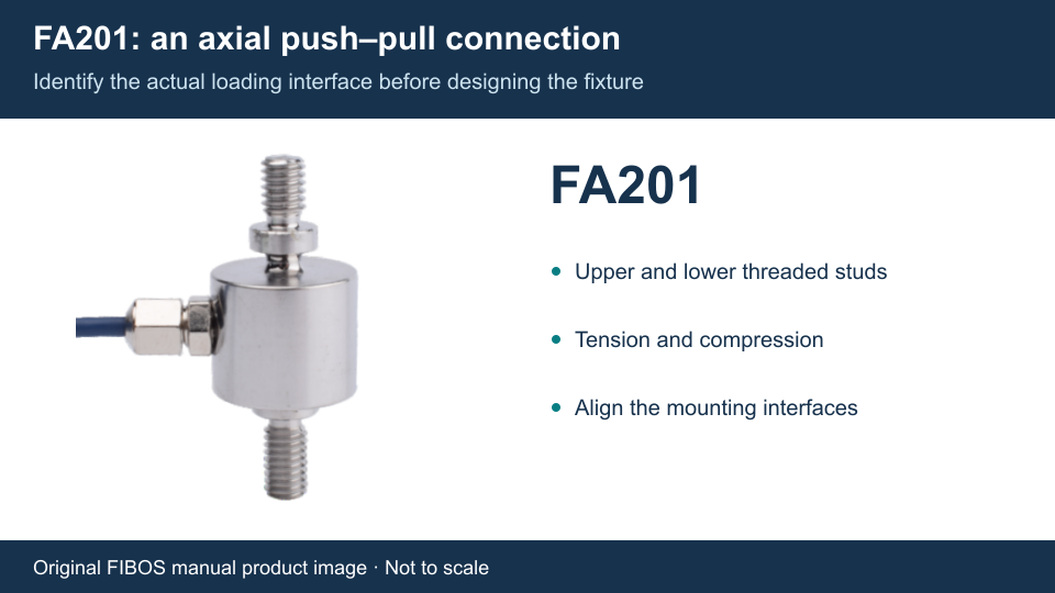
The FIBOS FA201 manual shows upper and lower threaded studs for bidirectional axial loading. This is a concrete example within the inline tension and compression force sensor family. The catalog name “rod end” does not mean that every model includes a spherical rod-end bearing or automatically compensates for misalignment.
FIBOS FA201 product image reproduced from its manual, showing threaded studs for an axial tension/compression connection. Not to scale.
· Column Force Sensors
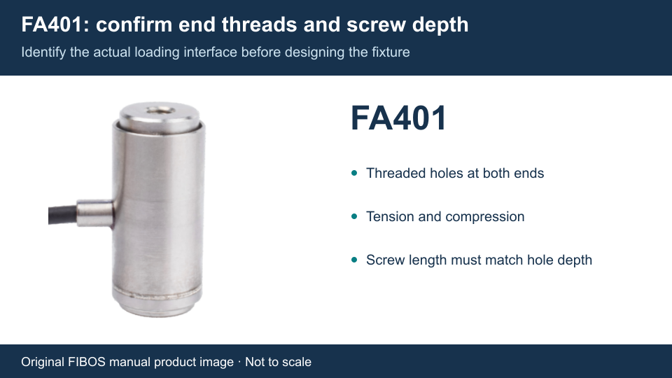
Column designs offer another axial mounting arrangement, often using threaded interfaces in a cylindrical body. The FIBOS FA401 manual shows threaded holes at both ends and tension/compression installation. It specifically calls attention to screw length relative to hole depth. Bottoming a screw or clamping the wrong surface can create an unintended load path.
Select column force sensors from the actual mounting and force requirements, rather than assuming that a column shape means high capacity or compression-only operation. Compact column force sensors and high-capacity column load cells serve different installation needs; the selected model drawing and loading specification decide the fit.
FIBOS FA401 product image reproduced from its manual. The drawing specifies threaded mounting at both ends and calls attention to screw length versus hole depth. Not to scale.
Design
Start here when…
Check before committing
Miniature & button
Compression must be measured in limited space
Loading point, body clearance, minimum useful force
Axial measurement suits a cylindrical mounting envelope
End interfaces, screw depth, load direction
Where Are Force Sensors Used?
· Press-Fit, Bonding, and Insertion–Extraction Force Monitoring
Assembly equipment can measure pressing force, contact force during bonding, or connector insertion and extraction force. A compression-only sensor may suit a one-direction pressing step, while insertion–extraction testing can require bidirectional measurement. Place the sensor so the relevant process force passes through it without a parallel mechanical bypass.
A force–displacement curve requires synchronized displacement or encoder data in addition to force. A force sensor alone cannot locate a force peak along the stroke. For multi-point pressing, a single sensor reports the resultant load through its path; separate measurements or a suitable mapping system are needed to assess spatial load distribution.
· Single-Axis Contact Force Monitoring in Robotic Assembly
A single-axis sensor can provide feedback for a defined pushing, gripping, or contact direction in a robotic fixture. Its usefulness depends on whether the fixture constrains the load to that axis. If the task needs separate lateral forces or moments, evaluate a multi-axis design instead of attempting to infer all components from one axial reading.
Closed-loop force control also needs compatible controller inputs, an actuator, and a control strategy. Sensor bandwidth, communication delay, filtering, and fixture compliance all influence the result. Validate the complete loop under representative motion and contact conditions before using it for a production process.
· Material Testing and University Research Setups
Research fixtures use force sensors to investigate tensile or compressive behavior, contact mechanics, friction, and small mechanisms. Define the expected specimen force and displacement before choosing capacity. For low-force work, cable motion, fixture friction, thermal changes, and mounting stress can be significant relative to the signal being measured.
A force sensor does not directly measure material stress or strain. Stress calculations require a defined specimen area and loading model; strain requires deformation or gauge-length information. Record the fixture, sampling settings, force calibration, and temperature conditions so the experiment can be repeated and interpreted correctly.
How Do You Choose the Right Force Sensor?
· Measurement Direction, Force Range, Preload, and Overload
Start with the largest credible physical load, including fixture weight, preload, process force, and transient peaks. Then identify the smallest force change that must be distinguished. Choosing capacity only from the normal displayed process value can miss loads that remain mechanically present after the display has been tared.
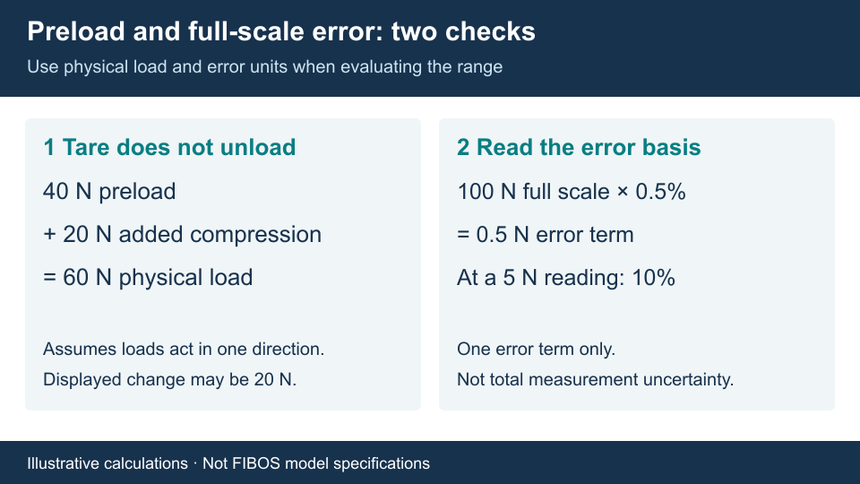
For example, a 40 N compressive preload followed by a further 20 N in the same direction creates approximately 60 N of physical load, even if the display was zeroed at 40 N. This illustrative case excludes impact and off-axis loading. A safe-overload specification is not a normal operating range or a promise of unchanged accuracy after an overload event.
· Accuracy, Resolution, and the Smallest Force You Need to Measure
Read the basis of every error specification: percent of full scale, percent of reading, or an absolute force value. In a hypothetical 100 N system, an error limit of 0.5% of full scale corresponds to 0.5 N. At a 5 N reading, that is equivalent to 10% of the reading for that error term alone. It is not a complete uncertainty estimate.
Resolution describes the smallest indicated or distinguishable change under stated conditions; it does not establish accuracy. Assess nonlinearity, hysteresis, repeatability, creep during the required hold time, thermal effects, and electronic noise. A display with more decimal places cannot recover force information that is lost in the mechanical or electrical measurement chain.
Illustrative calculations, not FIBOS model specifications. Taring does not remove preload, and a full-scale error term is not the same as a percentage of the current reading.
· Bandwidth, Stiffness, and Cyclic Loading
Define the event duration and the fastest force features that matter, such as a contact transient or short peak. Sensor natural frequency, installed resonance, usable measurement bandwidth, ADC sampling rate, and controller update rate describe different parts of the system. A natural-frequency figure must not be presented as the usable measurement bandwidth.
The fixture, attached mass, and sensor stiffness change the installed dynamic response. Select sampling and anti-alias filtering for the actual signal bandwidth, then verify peak capture and timing with a representative test. Repeated loading also requires evaluation of cycle amplitude, mean load, frequency, and fatigue suitability; static capacity alone is insufficient.
· Dimensions, Mounting Interfaces, and Environmental Conditions
Compare overall height, body diameter, threads or hole pattern, cable bend space, and assembly access. Check whether the proposed mounting leaves the sensitive surface free to work. For replacement projects, match the original mechanical interfaces and measurement direction before comparing electrical output and calibration factors.
Consider operating and compensated temperature ranges, washdown exposure, humidity, corrosion, and cable protection. An IP rating does not by itself establish chemical compatibility or suitability for repeated hot cleaning. Specify the actual exposure and duration instead of relying on a broad label such as “industrial environment.”
What Should You Check Before Installing a Force Sensor?
· Load Alignment, Contact Surfaces, and Force Shunts
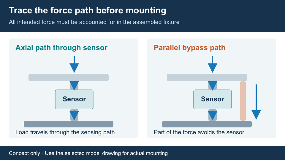
Draw the force path from the actuator or specimen through the sensor to the supporting structure. Use the specified loading surfaces and keep the intended measurement axis aligned. Check contact flatness, cleanliness, support rigidity, and screw engagement against the model drawing. The FA104 button and FA115 annular face illustrate why different designs require different contact conditions.
A force shunt is a parallel path that carries part of the load around the sensor. Contact with a housing, an unintended stop, or a fixture bridge can make the sensor report less than the total applied force. Some deliberate force-shunt arrangements are valid, but their relationship to total force must be calibrated in the assembled system. HBK’s guidance on force-shunt measurement discusses this distinction.
Conceptual load-path illustration, not a product mounting drawing. A parallel support can carry part of the load around the sensor and alter the reading.
· Side Loads, Bending Moments, and Mechanical Protection
Keep side forces, bending moments, and torsion within the selected model’s limits. A small offset can create a bending moment even when the main load is axial. Use guides or suitable joints where appropriate, but ensure their friction and supports do not bypass the measured load or introduce an unknown force.
Provide strain relief for the cable without pulling on the sensor body. Mechanical stops can limit excessive travel, but they must remain clear during valid measurements and must be designed for the machine’s expected fault loads. After assembly, inspect zero return and repeatability before accepting the fixture.
How Do You Connect a Force Sensor to a PLC or DAQ System?
· Matching mV/V Signals, Bridge Excitation, and Signal Conditioners
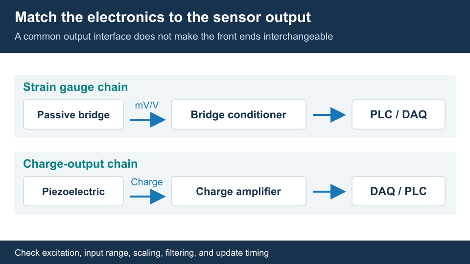
A passive bridge sensor needs stable excitation and an input designed for its small differential output. A general-purpose 0–10 V PLC input usually cannot directly replace a bridge amplifier. Check rated sensitivity, excitation limits, bridge resistance, input range, common-mode requirements, and whether the input provides four-wire or six-wire bridge support.
Use the exact model’s pinout rather than assuming wire colors are universal. Excitation wires, signal wires, and the shield have different functions. Higher excitation is not automatically better: it must remain within the sensor rating, and self-heating or the amplifier’s drive capability may limit the usable setting.
· Matching Piezoelectric Sensors with Charge Amplifiers
For a charge-output piezoelectric sensor, match charge sensitivity and expected force to the charge amplifier’s range. Verify reset behavior, drift, insulation condition, and the measurement time window. A standard strain gauge bridge amplifier is not interchangeable with a charge amplifier. Piezoelectric sensors with integrated electronics require their specified power and conditioning instead; PCB’s technical introduction distinguishes charge and integrated-electronics systems.
· Analog and Digital Outputs, Sampling, and Filtering
After signal conditioning, the system may deliver an analog voltage, a current loop, or digital data, depending on the supplied electronics. Match that interface to the PLC or DAQ hardware and confirm scaling, polarity, update timing, and overrange behavior. Communication protocol compatibility alone does not establish the attainable force accuracy or control-loop speed.
Separate raw ADC sampling, filtered output rate, and bus update rate when reviewing a data sheet. Filtering can reduce noise while also attenuating peaks and adding delay. Route signal wiring away from motor power cables and apply shielding and grounding according to the sensor and instrument instructions. Verify the finished system with the actual cable length and filter settings.
Conceptual measurement chains. Bridge excitation and charge amplification are different functions; analog or digital interfaces depend on the selected electronics.
How Are Force Sensors Calibrated and Checked?
· Zeroing vs. Calibration: What Is the Difference?
Zeroing or taring removes an indicated offset at a chosen reference condition. Calibration establishes the relationship between known applied forces and the system’s output, with documented conditions and measurement uncertainty where required. Zeroing does not correct sensitivity, hysteresis, or a wrong engineering-unit conversion, and it does not remove mechanical preload.
Choose calibration points that cover the intended operating range and required force directions. Where hysteresis matters, compare increasing and decreasing loads; where repeatability matters, repeat the loading sequence. Traceability and the calibration provider’s scope should match the project’s requirements. Set recalibration intervals from usage, overload history, stability records, and applicable quality requirements rather than assuming one interval suits every system.
A sensor positioned between loading fixtures in FIBOS workshop test equipment.
· Checking the Complete Measurement Chain Under Installed Conditions
Check the sensor, cable, conditioner, DAQ or PLC scaling, and displayed result together. Electronics can introduce gain and offset errors even when the sensor itself is stable. FUTEK’s calibration information describes why complete-system calibration includes the sensor, cable, and instrument.
Perform a separate installed verification using a suitable reference and representative force application. Check zero return, repeatability, loaded hold behavior, and any required dynamic response. If results change after mounting, investigate alignment, contact, force shunts, cable restraint, and thermal stabilization before applying a new scale factor. A scale adjustment cannot remove a changing mechanical error.
Frequently Asked Questions About Force Sensors
1. Can One Force Sensor Measure Both Tension and Compression?
Yes, when its design, mechanical connections, and specified calibration support both directions. An inline sensor with appropriate threaded interfaces can be a candidate. A compression-only button sensor cannot measure a pulling force through an unsecured contact surface. Check direction-specific ratings and the required calibration before selecting the model.
2. Can a Force Sensor Measure Weight?
It can measure the gravitational force transmitted through its load path. Converting that force to mass requires a suitable gravity value and a weighing arrangement that controls support and side-load effects. In moving equipment, acceleration also contributes to the measured force. Choose a weighing-specific load cell or module when platform support and weighing performance are the main requirements.
3. Why Does a Force Sensor Reading Drift Under a Constant Load?
Possible causes include sensor creep, temperature changes, fixture settling, cable forces, and electronic drift. The specimen itself may also relax, so the actual force may not remain constant. Compare unloaded and loaded behavior, allow appropriate thermal stabilization, and check the mounting and acquisition settings before attributing the change to the sensor.
4. Can I Replace an Existing Force Sensor with a Different Model?
A replacement can be evaluated by comparing loading direction, capacity, mechanical interfaces, deflection, overload limits, excitation, output sensitivity, pinout, and environmental requirements. Similar dimensions or nominal capacity do not prove compatibility. Update the conditioner configuration and verify the complete measurement chain with the replacement installed before accepting it.
5. When Is a Custom Force Sensor Worth Considering?
Consider customization when standard designs cannot meet a defined combination of space, mounting, load path, force range, environment, or output requirements. Provide drawings, normal and peak loads, the smallest force change of interest, timing requirements, and the intended electronics. These inputs support a feasibility review; sample testing is still needed to verify the proposed design.