You are here:Home » Blog » Single Point Load Cells: Types, Applications, and How to Choose
Single Point Load Cells: Types, Applications, and How to Choose
Views: 0 Author: Site Editor Publish Time: 2026-11-17 Origin: Site
A single point load cell is a weighing sensor designed to support a platform with one load cell and limit the effect of off-center loading within specified conditions. It is a practical option when a compact scale must weigh objects placed at different positions on its platform.
Choosing one requires matching the platform dimensions, total supported weight, measurement tolerance, and installation geometry—not just the nominal capacity.
What Is a Single Point Load Cell?
· What Does “Single Point” Mean in Platform Weighing?
“Single point” describes the use of one load cell beneath the weighing platform. It does not mean that the object must touch one small point or stay exactly above the sensor.
The platform transfers its weight and the payload through the sensor to the base. Off-center load compensation helps keep the indicated weight consistent as the object moves within the permitted platform area.
· How Do Single Point Load Cells Differ from Other Load Cell Designs?
A single point load cell may use a bending-beam or parallel-beam structure. The important distinction is the specified platform-weighing performance, including its response to eccentric loads.
A rectangular beam shape alone does not establish that a sensor can support a platform accurately. Before treating another beam sensor as interchangeable, check the manufacturer's platform limits, loading diagram, and off-center error specification.
How Does a Single Point Load Cell Work?
· How Strain Gauges Convert Load into an Electrical Signal
With the bridge excited by compatible weighing electronics, an applied load becomes a weight reading through the following chain:
Mechanical deformation: the load elastically deforms the sensing element, changing the resistance of its bonded strain gauges.
Bridge signal: the excited Wheatstone bridge produces a small differential voltage as those resistances change.
Weight indication: the weighing electronics read the signal and use the configured zero and span to display weight.
· How Off-Center Load Compensation Works—and Its Limits
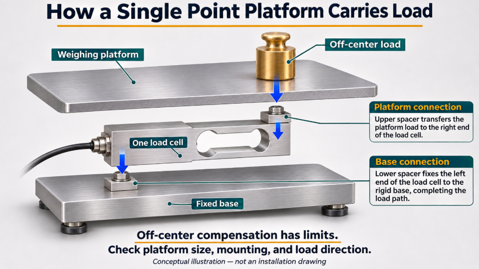
Moving a load toward an edge changes the bending and twisting moments applied to the sensor. The sensing geometry, strain-gauge arrangement, and factory adjustment reduce the influence of those position-dependent effects on the weight signal.
Compensation has limits. An oversized platform, flexible mounting, excessive side force, or incorrect fastening can still make readings depend on load position.
One sensor carries the platform and payload through two end connections. Exploded conceptual illustration; gaps separate the parts for explanation and are not installation clearances.
Where Are Single Point Load Cells Used?
· Bench Scales and Compact Weighing Platforms
Bench scales, counting scales, and parcel scales often need a simple platform that accepts objects in several positions. One suitable single point load cell can simplify the mechanical assembly and signal wiring.
For counting applications, verify the smallest useful part weight and variation between parts; a stable total weight reading alone does not establish reliable piece counting.
· Packaging, Filling, and Checkweighing Equipment
Single point load cells are used in packaging and automated weighing equipment. A filling station must measure weight while material flow, vibration, and connected services disturb the platform. A checkweigher has only a limited measurement window as a package crosses the weighing section.
In both cases, test the complete mechanism and electronics at the intended production speed rather than selecting from static accuracy alone.
· Laboratory and Custom Equipment Weighing Systems
A compact weighing platform can also support a laboratory fixture, a sample container, or a custom machine station. This is an application direction, not a claim that every single point sensor meets analytical-balance performance.
Before judging suitability for an experiment, define the required change in mass, observation time, temperature variation, and fixture weight.
Which Single Point Load Cell Design Fits Your Application?
· Aluminum or Stainless Steel: Material and Environmental Requirements
Choose the material together with the sealing method, cable entry, cleaning process, and temperature limits.
An aluminum model may suit a protected indoor machine. Where corrosion or frequent cleaning is a concern, evaluate a stainless steel design against the actual protection rating and chemical compatibility of the complete assembly.
· Low-Profile and Alternative Mounting Designs
Compare the complete dimensioned drawings. Mounting-hole pitch, thread size, loading height, spacer thickness, and cable exit direction can determine whether a sensor fits.
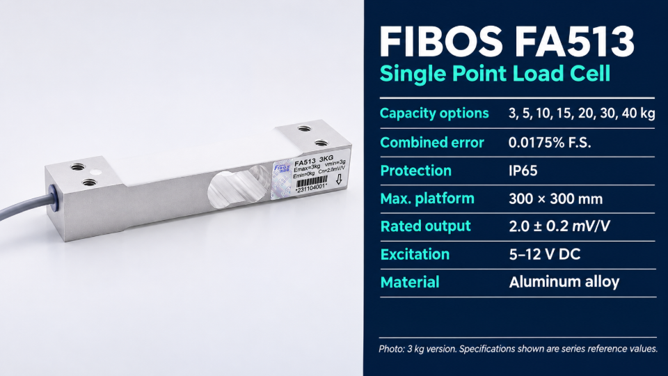
FIBOS's FA513 documentation lists an aluminum single point design with capacity options from 3 to 40 kg and a maximum platform size of 300 × 300 mm. These are model-specific reference values, not limits for the whole category.
For an initial mechanical review, compare the FA513 mounting arrangement with your platform drawing. Request the current drawing and specifications for the exact capacity before freezing the design. The label on the product photograph identifies the pictured capacity; it does not describe every version in the series.
FIBOS FA513 photo-based specification graphic: capacity options, combined error, IP65 protection, platform size, output, and excitation. The pictured label identifies a 3 kg version.
FA513 specification
Reference value
Capacity options
3, 5, 10, 15, 20, 30, 40 kg
Combined error
0.0175% F.S.
Protection
IP65
Maximum platform size
300 × 300 mm
Rated output
2.0 ± 0.2 mV/V
Excitation
5–12 V DC
Confirm the current specification for the capacity and installation selected. IP65 is an ingress-protection rating, not a claim of suitability for immersion or every cleaning process.
· Analog or Digital: Output and Integration Requirements
Analog bridge output is commonly specified in mV/V and needs compatible weighing electronics. A digital version includes conversion electronics; confirm its protocol, supply, and update behavior before connecting it to a controller.
Product names such as “smart” do not establish the interface. For example, the FA513 product page lists a sensitivity of 2.0 ± 10% mV/V; this specification describes a bridge output, not proof of a built-in digital communications interface.
How to Choose the Right Single Point Load Cell
· Select Capacity for Platform Dead Weight, Payload, and Loading Conditions
Start with everything carried by the sensor: platform, brackets, fixtures, containers, and maximum payload. Taring the display subtracts a value electronically; it does not remove physical load or restore capacity.
Then assess loading impact, acceleration, and credible misuse. Choose operating margin from those conditions and the manufacturer's limits rather than applying one universal multiplier.
Illustrative Calculation: Capacity Headroom
Platform and fixture: 4 kg
Maximum product: 12 kg
Static supported mass: 4 + 12 = 16 kg
With a 20 kg sensor: 4 kg of nominal static headroom
This arithmetic is only a starting point: platform limits, impact, eccentric loading, accuracy, and overload protection still require review. Safe overload is a protection limit, not an additional normal weighing range.
· Match Platform Dimensions to the Specified Limits
Check both platform dimensions, the orientation relative to the sensor, and the prescribed position of the platform center.
Do not convert a rectangular platform limit into an equivalent area: a long narrow platform can produce different moments from a square platform with the same area. If the drawing does not resolve an unusual geometry, provide its dimensions and worst-case loading positions to the manufacturer for evaluation.
· Evaluate Accuracy at the Smallest Weight You Need to Measure
Write the acceptance tolerance in mass units, then examine the error contributions across the required operating range:
Nonlinearity and hysteresis
Repeatability and creep
Temperature effects
Off-center error
Electrical noise
Display resolution is only the smallest displayed increment; it is not the same as measurement accuracy. Likewise, a component accuracy class does not by itself validate the assembled machine.
Error-Budget Example
0.02% of a 20 kg full scale = 4 g
Measuring a 100 g sample: that one contribution could already matter
This is an illustrative conversion, not an FA513 specification or a prediction of total system error. Avoid adding every maximum specification blindly; determine which terms apply and how they are defined.
· Check Settling Time for Moving Loads and Short Weighing Cycles
Specify how soon a usable reading must be available after loading and how much error is allowed at that instant. Sensor stiffness, platform mass, conveyor vibration, sampling rate, and digital filtering all affect the result.
A high natural frequency or fast data rate alone does not guarantee a short usable weighing cycle. Verify response with representative loads on the assembled equipment.
How Should You Install a Single Point Load Cell?
· Identify the Fixed End, Loading End, and Load Direction
Before fastening, identify the fixed end, loading end, load arrow, and platform-center reference on the model-specific drawing. Support the assembly throughout installation so tightening does not twist or overload the sensing section.
Attach the fixed end to the base as shown in the mounting drawing.
Attach the loading end to the supported platform.
Verify the platform-center position and load direction before removing temporary support or applying a test load.
Do not assume that the cable end, label position, or appearance establishes the correct orientation.
· Check Mounting Surfaces, Spacers, Fasteners, and Clearances
Surfaces: flat and sufficiently rigid, with the spacers specified for the design.
Fasteners: confirm bolt size, engagement depth, and tightening torque from the current instructions.
Clearances: leave room for normal sensor deflection and platform movement.
A screw that bottoms out, a warped bracket, or a platform rubbing the cover can introduce an error even when the sensor is correctly wired.
· Prevent Force Shunts, Side Loads, and Overload Damage
A force shunt is an unintended path that carries part of the load around the sensor. Common causes include:
A rigid pipe or tight cable
A guard touching the platform
Accumulated debris
Route services with appropriate flexibility and strain relief, and make sure the platform remains mechanically free throughout its travel. Check this with containers, hoses, and covers installed—not only on an empty bench assembly.
Where overload stops are required, set their clearance using the manufacturer's deflection and installation guidance. A stop must not touch during the accepted weighing range, yet must engage before damaging displacement occurs.
How Do You Connect a Single Point Load Cell to Your Measurement System?
· Check Excitation, Rated Output, and Four- or Six-Wire Connections
Check excitation positive and negative, signal positive and negative, and any sense connections against the exact wiring diagram. Wire colors vary between manufacturers and models.
Four-wire cells carry excitation and signal pairs. Six-wire cells add sense leads, which compatible electronics can use to monitor bridge excitation.
Follow the indicator's instructions when adapting one wiring arrangement to another.
Signal-Level Example
Nominal 2 mV/V bridge × 5 V excitation ≈ 10 mV full-scale signal (before zero offset and tolerances)
A conventional process signal: 0–10 V
The bridge signal is far below a 0–10 V process signal. Do not connect it directly to a conventional PLC voltage input and expect useful weighing performance.
· Match the Signal Conditioner to Your Indicator, PLC, or DAQ
Select an input designed for strain-gauge bridges or use a suitable weighing amplifier. Check:
Excitation supply and input range
Usable noise level and update rate
Calibration functions
An output the receiving controller supports
Keep low-level signal wiring away from motor and inverter cables, provide strain relief, and follow the equipment's shielding and grounding instructions.
How Do You Calibrate and Verify a Single Point Weighing System?
· Calibrate Zero and Span with the Platform Installed
Complete the mechanical assembly and allow the electronics to stabilize as specified.
Check that the empty platform is free of contact.
Set zero with the normal platform and fixtures installed.
Apply suitable reference masses and calibrate span according to the instrument procedure.
Verify additional points across the intended range.
The reference masses and method must be appropriate to the required tolerance. A sensor's factory calibration does not include errors introduced by your platform, wiring, amplifier, or mounting.
Zero and span setup sets the instrument's weight indication. Verification checks whether the assembled system meets its acceptance criteria. Record the reference masses, setup, and results.
· Verify Center and Corner Readings, Repeatability, and Zero Return
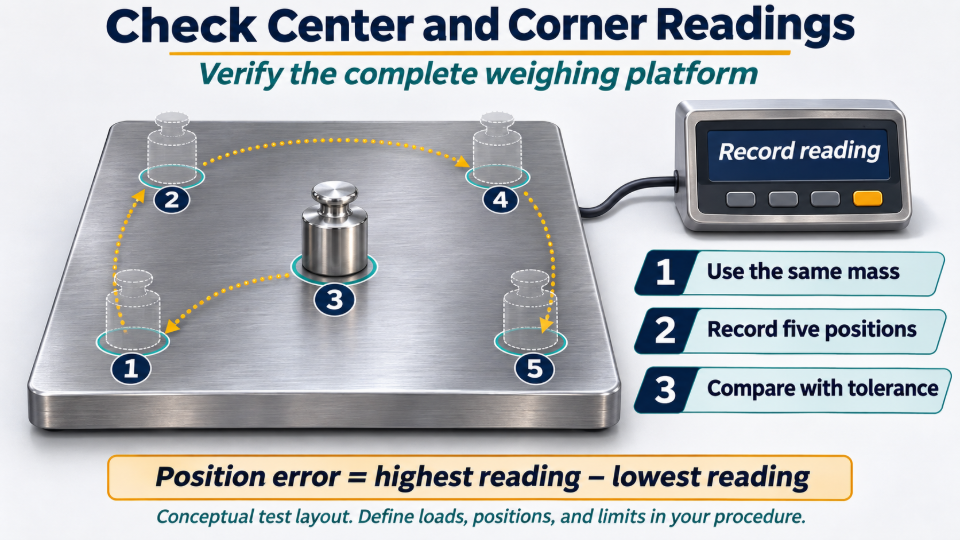
Place the same suitable test mass at the platform center and at defined corner or edge positions within the permitted loading area.
Record the locations, applied mass, indicated values, and settling time.
Calculate the difference between the largest and smallest indication and compare it with the project's position-error allowance.
Keep the mass fully supported and avoid dragging or dropping it.
Repeat loading and unloading to check repeatability and zero return. Where relevant, hold a constant load to assess time-dependent drift and run the machine with its motors, airflow, and material handling active.
Define the test load, dwell time, number of repetitions, and pass limits before testing. This engineering check is not a substitute for any formal approval procedure applicable to the finished scale.
Move the same test mass between defined center and corner positions, then compare readings with the project tolerance. Conceptual test layout.
Troubleshooting quick reference: check mechanical causes first, then electrical and calibration causes.
Issue
First mechanical check
Then check
Position-dependent readings
Platform size, rubbing, base stiffness
Mounting torque and specified orientation
Zero changes after a cycle
Debris, hose force, platform contact
Warm-up, temperature, electrical zero
Stable offset after impact
Permanent deformation or shifted mounting
Sensor condition and recalibration
Unstable readings with motors running
Vibration and cable movement
Shielding, input noise, filter settings
To discuss a FIBOS single point load cell for a new machine or a replacement, provide:
Maximum payload, plus platform and fixture weight
Platform dimensions and mounting drawing
Required tolerance and output interface
Operating environment
For a replacement: the original model and wiring information, so mechanical and electrical suitability can be evaluated
Frequently Asked Questions About Single Point Load Cells
1. Does the Load Have to Be Placed at the Center of the Platform?
No. A correctly installed single point load cell is designed to limit position-related error within its specified platform and loading conditions. Corner readings should still be verified on the assembled scale because platform stiffness, interference, and installation errors can affect the result.
2. Can You Use a Platform Larger Than the Specified Maximum Size?
Do not assume that a lighter payload makes an oversized platform acceptable. A larger lever arm changes the moments on the sensor. Ask the manufacturer to evaluate the actual geometry and loading cases, or choose a sensor or multiple-cell arrangement specified for the platform.
3. When Should You Use Multiple Load Cells Instead of One?
Consider multiple load cells when the platform geometry, total load, support arrangement, or eccentric loading exceeds the limits of a suitable single point design. Multiple sensors introduce load-sharing and signal-combination requirements, so the support structure and electronics must be designed together.
4. What Should You Check When Replacing an Existing Single Point Load Cell?
Compare capacity, permitted platform size, hole pattern, loading height, load direction, rated output, excitation, wiring, and environmental limits. Matching dimensions or nominal sensitivity does not establish full compatibility. Recalibrate and verify the complete scale after replacement.
5. Why Does the Reading Change When the Same Weight Is Moved Across the Platform?
Check platform dimensions and orientation first, then look for rubbing, a flexible base, loose fasteners, tight services, or an engaged overload stop. Confirm the sensor is intended for single point platform weighing. If the installation is correct and the error persists, document the corner-test results for technical review.