You are here:Home » Blog » Piezoelectric Force Sensors: Types, Applications, and How to Choose
Piezoelectric Force Sensors: Types, Applications, and How to Choose
Views: 0 Author: Site Editor Publish Time: 2026-11-11 Origin: Site
Piezoelectric force sensors convert mechanical force into an electrical charge signal. Their high stiffness makes them useful for capturing impact forces, rapid compression or tension, and changes in force during machine cycles. With suitable signal conditioning, they can also measure slowly changing or temporarily held forces over a defined measurement window.
Start with the force event you need to record: its direction, peak value, duration, and smallest meaningful change. A sensor that captures a brief impact accurately may be unsuitable for monitoring a constant clamping force for hours. The sensor, mounting arrangement, amplifier, and data acquisition settings must be selected together.
What Is a Piezoelectric Force Sensor, and How Does It Work?
· From Applied Force to an Electrical Charge Signal
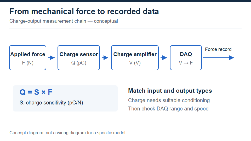
Inside a quartz force sensor, force applied to the sensing element produces charge through the direct piezoelectric effect. For a specified loading direction, the ideal relationship is Q = S × F, where Q is charge in picocoulombs (pC), S is charge sensitivity in pC/N, and F is force in newtons (N). The calibration value for the actual sensor should be used when converting a recorded signal into force.
A charge amplifier converts this high-impedance signal into a usable voltage. Some piezoelectric sensors instead contain integrated electronics and provide an IEPE signal. Force is the measured quantity; the charge or voltage is its electrical representation. A piezoelectric force sensor should therefore not be confused with a fluid pressure sensor simply because both use piezoelectric materials.
A charge-output sensor needs compatible charge conditioning before its signal reaches an ordinary voltage acquisition input.
· Piezoelectric vs. Strain Gauge Force Sensors: When to Choose Each
Piezoelectric sensors are strong candidates when the measurement requires a stiff load path and the capture of fast force changes. Strain gauge force sensors measure elastic deformation through a change in electrical resistance and are often the more straightforward choice for sustained static loads. Both technologies can measure changing forces within their specified limits; the decision should follow the required duration, response, and uncertainty rather than a simple static-versus-dynamic label.
Can Piezoelectric Force Sensors Measure Static Force?
· Dynamic, Quasi-Static, and Long-Term Static Measurements
They can measure quasi-static force when the measurement chain keeps signal decay and drift within the allowed error for the required time. This is different from indefinitely maintaining an accurate reading of a constant load. A catalog reference to static calibration does not establish suitability for long-term weighing or continuous clamp-force monitoring.
Task
Signal
Selection check
Dynamic
Force pulse or changing waveform
Preserve both fast and slow parts.
Quasi-static
Slow ramp or brief hold
Check drift and decay over the full test.
Long-term static
Constant load over an extended period
Prefer a strain gauge system unless the full chain is validated.
· How Measurement Duration, Time Constant, and Drift Affect Results
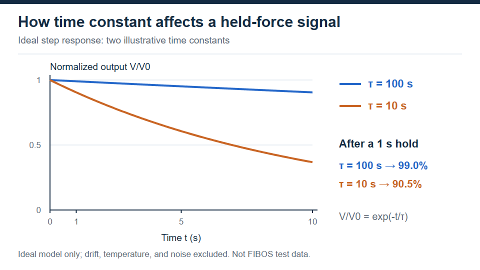
Time constant describes the low-frequency behavior of the measurement electronics. In an ideal first-order system, a step signal decays as V(t) = V0 × exp(-t/τ), where τ is the time constant. A longer time constant reduces decay during a finite hold, but leakage-related drift and temperature effects still need to be checked. Kistler distinguishes these operating modes in its time constant guide.
For illustration, a 1-second hold in an ideal system with a 100-second time constant loses about 1% of its initial signal through this mechanism alone. This calculation excludes noise, thermal effects, calibration error, and other drift. It is not a performance claim for any FIBOS model. Define the acceptable force error and test the complete duration instead of assuming that a universal number of seconds applies to all piezoelectric sensors.
In this ideal first-order model, a longer time constant reduces decay during a finite hold; actual measurements must also account for drift and other errors.
Which Piezoelectric Force Sensor Design Fits Your Application?
The following designs are represented in the FIBOS 2026 product catalog. These groups describe different selection considerations: a washer is a mechanical form, while tension–compression and three-axis describe measurement directions. They are not mutually exclusive classifications.
· Force Washers for Preloaded Assemblies
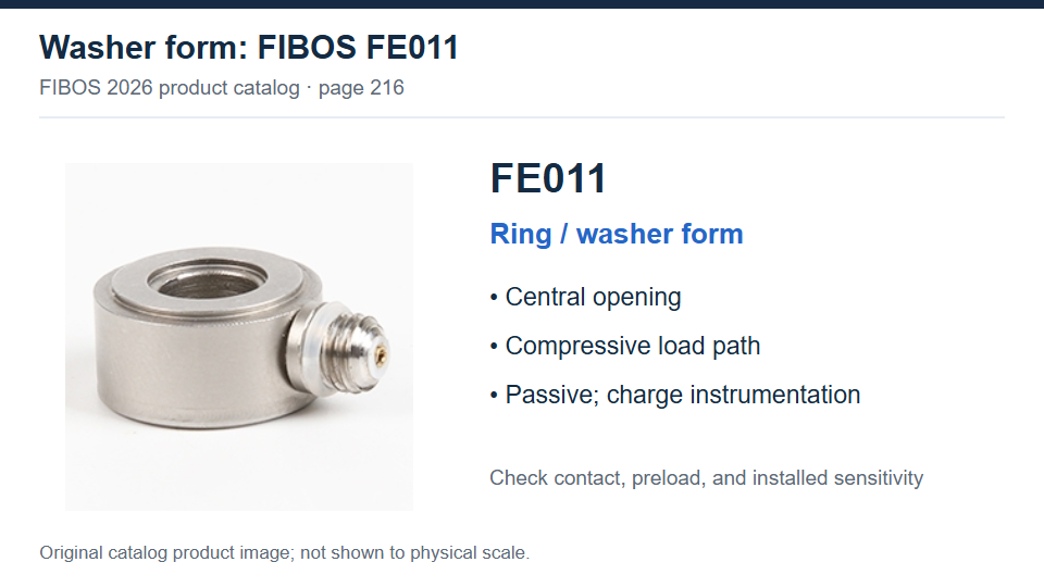
A force washer places an annular sensing element around a central opening. It can fit a compressed assembly where a bolt or shaft passes through the center. FIBOS FE011 is identified as a ring-structure piezoelectric sensor, and its catalog page specifies passive operation with charge instrumentation. Its drawing provides the dimensions needed to evaluate the opening and bearing surfaces.
The washer must sit in the intended load path; simply fitting around a bolt does not mean it measures the entire joint force. Check how the bolt and surrounding parts share load, and determine the installed sensitivity. For the broader mechanical selection issues, see the FIBOS through-hole and donut force sensor guide.
FIBOS FE011 uses a ring structure. Evaluate the central opening, bearing surfaces, and installed load path together.
· Compression and Tension–Compression Force Sensors
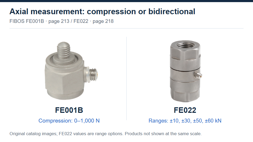
For a single axial load, check whether the sensor is specified for compression only or for both tension and compression. The FIBOS FE001B catalog page lists a 0–1,000 N measuring range and a compact threaded structure. FE022 provides bidirectional measurement, with ±10, ±30, ±50, and ±60 kN range options listed in the catalog. These are examples of different load capabilities, not interchangeable mounting designs.
A tension–compression installation needs a load connection that transmits both directions without looseness or unintended bending. Confirm thread size, engagement, loading direction, and the calibration sensitivity for each direction. A compression-only range must not be treated as a tensile rating merely because the housing has threads.
FE001B and FE022 illustrate different axial measurement capabilities. Confirm the load direction and model-specific mechanical connection.
· Three-Axis Piezoelectric Force Sensors
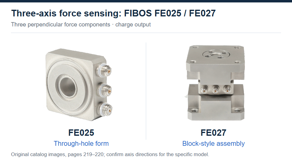
Choose a three-axis sensor when the useful result includes Fx, Fy, and Fz rather than one axial force. FIBOS FE025 and FE027 are both described as measuring three mutually perpendicular force components simultaneously. Their catalog pages identify charge output and show separate X/Y and Z specifications. FE025 uses a through-hole form; FE027 has a block-style mounting arrangement.
Record the sensor coordinate directions before assembly and assign each channel in the acquisition software. Request the applicable cross-talk and calibration information for the intended loading condition. Three force channels do not establish six-axis force-and-torque capability, and the same force limit should not be assumed for every axis.
FE025 and FE027 measure three perpendicular force components. Verify the coordinate mapping and each axis specification before integration.
Where Are Piezoelectric Force Sensors Used?
· Press-Fit Assembly, Stamping, and Joining Process Monitoring
In a press-fit cycle, the useful signal may be the rise in force, a peak near final seating, or an unexpected change before the part reaches its target position. Place the sensor where that process force is transmitted and synchronize force with displacement if the acceptance criterion depends on insertion position. Stamping and other joining operations similarly require a defined measurement window and a repeatable mounting condition.
For a cycle with a holding stage, verify the plateau as well as the peak. A system that identifies the maximum force correctly can still misrepresent the held force because of signal decay. Set the reset point consistently before the force event and outside the interval used for acceptance.
· Impact, Drop, and Repeated Dynamic Loading Tests
For an impact test, estimate the force pulse and its rise time before choosing the sensor range and acquisition settings. A small dropped object does not necessarily produce a small peak force: stopping distance and contact stiffness affect the event. Inspect the fixture and recorded waveform for ringing, clipping, and repeated contact. Repeated dynamic loading also requires confirmation of the permitted load history; a safe-overload figure alone is not a fatigue-life rating.
· Cutting Force Measurement and Laboratory Test Rigs
A three-axis measurement can help separate force components in a cutting experiment or a research fixture. Define whether the required result is an individual component, a resultant force, or a change relative to a preloaded baseline. A sensor mounted beneath a fixture does not automatically isolate the desired contact force: fixture inertia, structural motion, and other load paths may contribute.
How to Choose the Right Piezoelectric Force Sensor
· Force Range, Preload, and Overload Margin
Write down the highest and lowest mechanical loads at the sensor, including preload and transient peaks. Electrical zeroing changes the reference reading; it does not remove the preload or restore mechanical capacity. As a simplified bookkeeping example, a 2 kN compressive preload plus a 3 kN additional compressive event puts 5 kN through the sensor if both loads follow the same path. Actual washer assemblies may share that additional load with a bolt or surrounding structure.
For tension measured through a preloaded assembly, check how much compression remains at maximum unloading and follow the specified mounting method. Do not choose a universal preload percentage or use the safe-overload limit as the normal operating range. Send the expected load history and assembly drawing for model-specific review.
· Minimum Force, Sensitivity, and Measurement Uncertainty
Specify the smallest change that would affect your decision. For example, distinguishing a 5 N assembly-force difference is a different task from simply detecting a 1 kN peak. Ask whether the stated error is relative to full scale or to the reading, and evaluate baseline noise and drift in force units. Increasing amplifier gain makes the voltage change larger, but does not remove mechanical errors or establish a smaller guaranteed measurement limit.
Build the uncertainty assessment around the installed chain: calibration, repeatability, alignment, force sharing, electronics, and the measurement duration. For three-axis work, include the influence of loads on the other channels. A catalog linearity figure by itself is not the uncertainty of the finished machine.
How Should You Install a Piezoelectric Force Sensor?
· Contact Surfaces, Alignment, and Off-Axis Loads
Check the model drawing for the intended loading surfaces and mounting details. Mating parts should support the specified bearing area and transmit force in the intended direction. Dirt, uneven contact, and edge loading can make a nominally axial test introduce bending or local stress. Confirm that adapters do not contact the connector and that cables have clearance through the machine stroke.
During commissioning, compare repeated cycles without changing the fixture. If a small repositioning changes the measured peak substantially, investigate the mounting and load path before adjusting the software scale. For dynamic tests, also check whether an added adapter changes the response of the assembled fixture.
· Preload, Force Shunts, and Installed Sensitivity
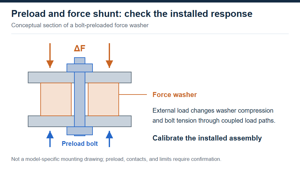
Preload keeps the intended contact surfaces engaged. In a bolted washer installation, however, the bolt also forms a parallel load path. Part of an external force change can pass through that path, so the sensitivity of the installed assembly can differ from the sensor calibration value. Kistler discusses this distinction in its ring force transducer installation manual.
Determine the conversion factor with the final bolt, spacers, supporting parts, and preload condition in place. Record those conditions with the calibration results. Changing a spacer or bolt can change force sharing even when the sensor and amplifier are unchanged. Use the specific sensor instructions to establish preload; a rule from another model is not sufficient.
A preload bolt changes the installed load path. Establish sensitivity with the final bolt, supports, and preload condition in place.
How Do You Connect the Sensor to Your Measurement System?
· Charge Output vs. IEPE: Matching the Signal Conditioner
A charge-output sensor normally connects to a charge amplifier or a DAQ input specifically designed for charge signals. An ordinary voltage input or strain gauge bridge amplifier is not a substitute. An IEPE sensor uses a compatible constant-current supply and voltage readout arrangement. Connector fit alone does not establish electrical compatibility. PCB explains charge and integrated-electronics signal conditioning.
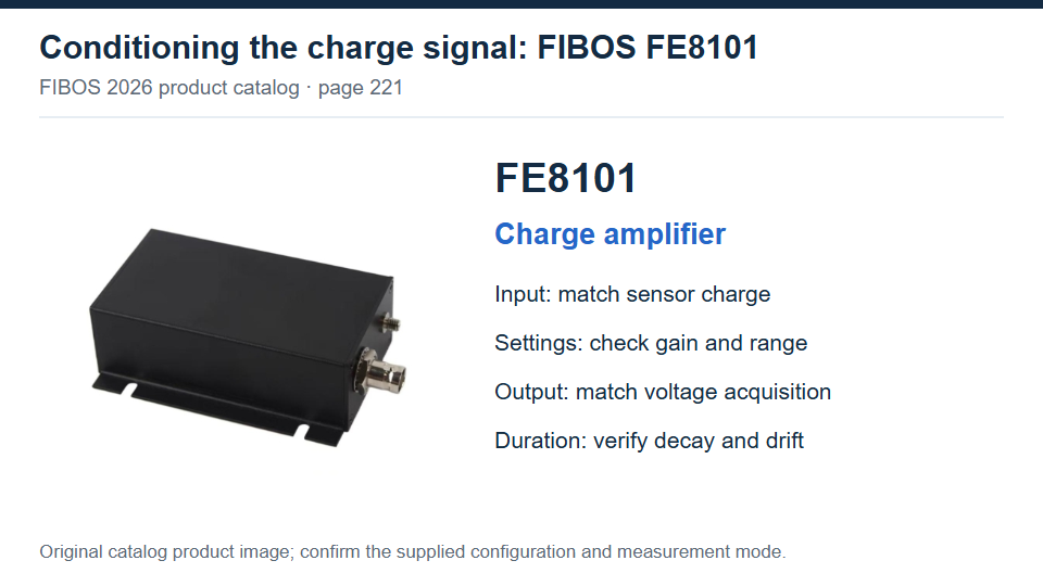
The FIBOS examples in this article are based on charge-mode catalog information. FE011 explicitly calls for charge instrumentation, and FE025/FE027 specify charge output. Select the input for the specified charge output; do not assume these models contain IEPE electronics. FE8101 is a FIBOS charge amplifier, not another force sensor.
FE8101 is a charge amplifier. Match the supplied configuration to the sensor charge signal, acquisition input, and measurement window.
· Charge Amplifier Range, Gain, and Time Constant
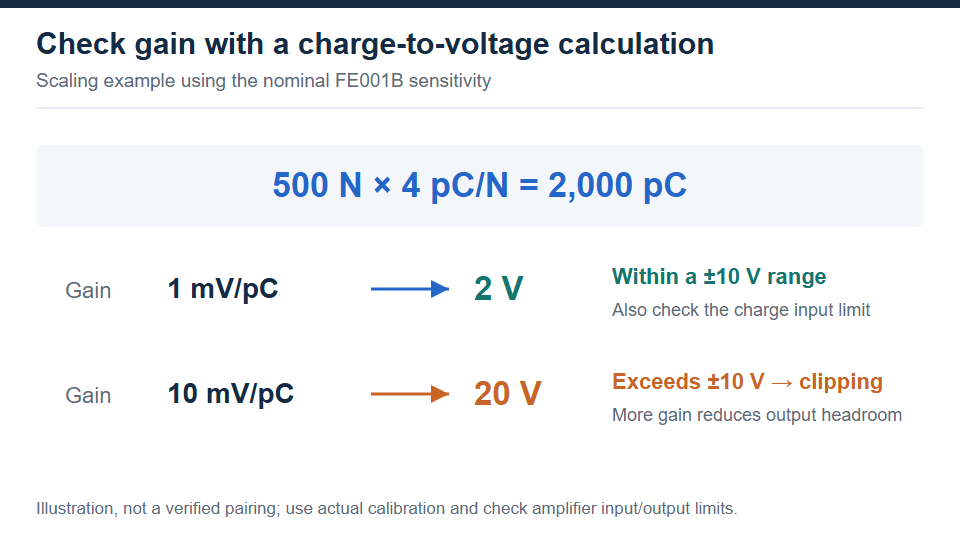
Calculate expected charge before setting amplifier gain. Using the FE001B nominal sensitivity of 4 pC/N from the 2026 catalog, a 500 N force change produces a nominal 2,000 pC. With an illustrative amplifier setting of 1 mV/pC, the output change is 2 V. At 10 mV/pC, the same event would demand 20 V and would clip an amplifier limited to ±10 V. This is a scaling example, not verification of a particular sensor-amplifier configuration.
For the same nominal charge signal, increasing gain from 1 to 10 mV/pC raises the requested output from 2 to 20 V; a ±10 V output stage would clip.
Check the charge input limit, output swing, gain setting, and measurement mode together. A long measurement window also needs appropriate low-frequency response and drift performance. The FE8101 catalog lists adjustable gain and a voltage output, but it does not establish a guaranteed hold duration for your fixture. Confirm the exact supplied configuration and required measurement window. Kistler summarizes the broader charge amplifier selection criteria.
· DAQ and PLC Interfaces, Sampling, and Low-Noise Cabling
Connect the conditioned output to a DAQ or PLC input with the correct voltage range, grounding arrangement, and acquisition speed. Do not assume a charge amplifier provides 4–20 mA or a digital fieldbus unless that output is specified. For a fast event, check the analog input update rate and filtering as well as the PLC program cycle. If the control system cannot preserve the waveform, use a suitable acquisition channel and pass a validated result to the controller.
Choose sampling and anti-alias filtering for the signal you need to retain; raising the sample rate does not correct an unsuitable analog filter. Secure charge-mode cables so that machine motion does not flex them unnecessarily, use the specified low-noise cable, and keep high-impedance connections clean and dry. Document channel scaling and polarity with the data file so another engineer can reconstruct force from the recorded voltage.
How Do You Calibrate and Verify the Complete Measurement Chain?
· Calibration After Installation or Changes to the Load Path
A sensor certificate describes specified calibration conditions. Commissioning must also establish how the final assembly converts applied force into the recorded result. Where a force shunt exists, compare the installed system with a suitable calibrated reference through the intended load path. Use multiple force points and repeated loading cycles appropriate to the working range, and keep each reading within a validated measurement window.
Save the sensor serial number, reference instrument, mounting condition, preload, amplifier settings, DAQ scale, and test timing. Recheck after changes that can affect force sharing or conversion, including a new sensor, altered fixture, changed amplifier gain, or revised software scale. Electrical charge injection can check the electronics, but cannot by itself verify the mechanical load path.
· Checking Zero Drift, Signal Decay, and Dynamic Response
Before accepting the installation, define measurable pass criteria: the allowed baseline change over the cycle, the allowed error during a hold, and the acceptable variation in repeated peaks. Check baseline behavior with the fixture mechanically stable, then apply a controlled reference load using the same reset and acquisition sequence planned for operation. A hold test alone cannot distinguish true load relaxation from electrical decay without an independent reference.
For dynamic verification, inspect raw data for clipping and ringing, compare results at appropriate filter settings, and verify the assembled fixture response with a suitable method. Set acceptance limits before comparing candidate sensors. When requesting a FIBOS model review, provide the load history, mounting drawing, smallest force change, measurement duration, and existing amplifier or DAQ details. For replacement projects, include the original model and calibration information; matching nominal capacity alone does not establish compatibility.
Frequently Asked Questions
1. Do Piezoelectric Force Sensors Need a Power Supply?
A passive charge-output sensing element generates charge without bridge excitation, but its charge amplifier and acquisition electronics need power. IEPE sensors also need the specified constant-current supply for their integrated electronics. Check the actual signal type before connecting power; a passive charge input is not an IEPE supply connection.
2. Can a Piezoelectric Force Sensor Measure Small Force Changes Under a Large Preload?
Potentially, if the sensor remains within its mechanical limits and the complete chain resolves the required incremental force. Establishing a new electrical baseline under preload can allow suitable electronics to focus on the subsequent change. Check charge range, noise, drift, and force sharing; zeroing does not remove preload or guarantee a particular resolution.
3. Is Resonant Frequency the Same as Usable Measurement Bandwidth?
No. Resonant frequency describes a mechanical resonance, while usable bandwidth is the frequency interval in which the installed system meets the required response tolerance. Added mass and fixture stiffness affect the mechanical response; the amplifier and filters also constrain the result. Do not use a catalog resonance value as a guaranteed flat measurement bandwidth. PCB discusses force sensor frequency response and installation.
4. Can You Replace an Existing Force Sensor Without Changing the Amplifier?
Only after checking signal type, sensitivity, charge range, polarity, connector wiring, and the required measurement mode. Mechanical fit and load direction must also match the application. Update the conversion settings and verify the installed chain with a reference load. The same nominal force range does not establish direct replacement or equivalent performance.
5. Why Does the Signal Change When the Sensor Cable Moves?
Movement of a high-impedance charge cable can generate unwanted electrical charge, often called triboelectric noise. First check that movement is not also applying real force to the sensor or connector. With the mechanical load stable, compare the signal before and after securing the specified low-noise cable. Inspect connection cleanliness and grounding before treating every spike as a process force.