You are here:Home » Blog » Bolt Preload Measurement and Monitoring with the FIBOS FA115
Bolt Preload Measurement and Monitoring with the FIBOS FA115
Views: 0 Author: Site Editor Publish Time: 2026-11-16 Origin: Site
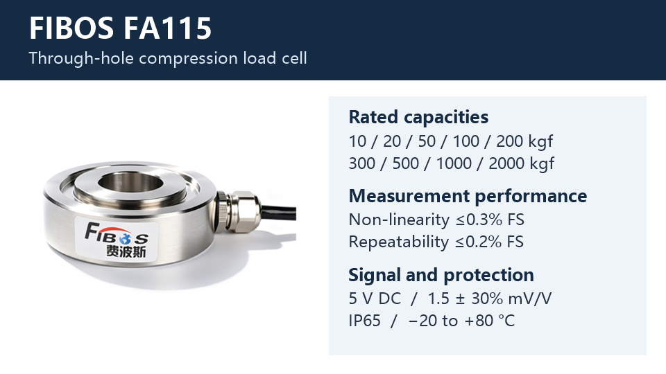
Measuring bolt preload during tightening helps you verify that a joint reaches its target clamp force. Monitoring the joint in service helps you decide when a loss of clamp force warrants inspection. The FIBOS FA115 is a through-hole compression load cell for applications where the fastening or tooling arrangement can route axial reaction force through the sensor.
The FA115 is offered in nine capacities from 10 to 2,000 kgf (approximately 0.098 to 19.6 kN). Non-linearity is ≤0.3% of full scale, and repeatability error is ≤0.2% of full scale. The sensor is rated IP65 and operates from −20 to +80 °C.
Measuring Bolt Clamp Force During Tightening
Tightening stretches the bolt and compresses the parts it holds together. Some of the applied torque goes into overcoming friction at the threads and bearing surfaces. Changes in lubrication or surface condition can therefore produce different clamp forces at the same torque setting. NASA torque–tension test report
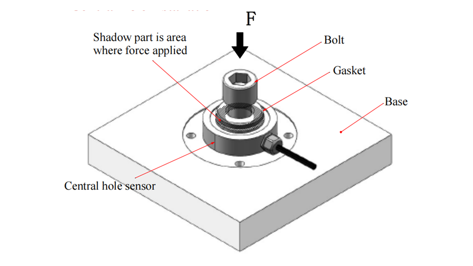
In a test fixture or an instrumented joint, the bolt passes through the center of the FA115. The bearing surfaces load the sensor in compression as the bolt tightens. With the sensor seated squarely and the full axial clamping load passing through its sensing surfaces, the force reading can be compared with the joint's target clamp force.
Figure 2. FA115 installation diagram showing the loaded contact area and axial force direction.
Record the torque and force together to characterize a tightening procedure, or record the force after the tool is released to check the remaining clamp load.
Adding a load cell changes the height and stiffness of the assembly. Check the fit and load path against the joint drawing before using fixture results to set limits for production assembly or maintenance.
Tracking Preload Loss in Wind Turbine Bolted Joints
An online monitoring system can flag a sustained change in load at an instrumented joint. A published wind turbine study used ultrasonic sensors to track bolts connecting the hub and pitch bearings over seven months. A compression load cell uses a different measurement method and can be evaluated where the joint design provides a suitable bearing surface and the loads fit the sensor's range. Wind turbine preload monitoring study
The acquisition system converts the FA115 bridge output into force. Use the readings to track changes in three steps.
Step
What to check
Record a baseline
Capture the stabilized clamp force after tightening, along with operating state and temperature.
Compare readings
Compare similar conditions and account for operating loads, temperature effects, and sensor drift.
Flag a sustained drop
Apply the project's force limit and duration criteria to trigger inspection. Inspect the joint before assigning a cause.
The highest standard FA115 capacity is approximately 19.6 kN. One wind turbine bolt inspection study used an M36 test bolt loaded to 300 kN, illustrating why the required force range must be checked for each location. For permanent installation, also verify cyclic durability, long-term drift, environmental protection and the effect of the sensor on the joint. FA115 specifications · Wind turbine bolt inspection study
Monitoring Force and Stroke in Blind Rivet Installation
During blind riveting, the tool pulls the mandrel while its nosepiece reacts against the rivet head. One published tool design places a ring load cell in that reaction path and uses a separate displacement sensor to track tool travel. Recording force and stroke together lets the controller compare the setting curve with acceptance windows established using verified assemblies. Blind rivet installation patent publication · GESIPA process monitoring
The FA115 can be evaluated for the force channel if the tool provides a suitable compressive load path. Check the space around the moving parts, the peak reaction force and whether the acquisition system can resolve the relevant events within one setting cycle.
The force–stroke curve describes the installation process. If residual clamp force is an acceptance criterion, verify it separately with a suitable test.
Selecting an FA115 for Your Joint or Tool
The FA115 uses a 17-4PH stainless steel sensing element. Its nominal excitation is 5 V DC, and its rated output is 1.5 ±30% mV/V. Use a bridge-compatible input that reads millivolt signals. FA115 specifications
Selection item
What to send FIBOS
Force range
Target clamp force or expected riveting force, plus the highest load the sensor will see.
Mechanical fit
A drawing showing bolt or tool dimensions, available space, and bearing surfaces.
Data acquisition
Required recording rate for a tightening or riveting cycle, or planned monitoring duration for an in-service joint.