FIBOS has completed third-party compression calibration of its FA4221-10MN force sensor at Fujian Metrology Institute, with recorded test forces reaching 10,000 kN. The calibration was conducted on November 3, 2026.
For this 1,000-tonne-class sensor, the calibration provides measured force-to-output data and documented traceability. Engineers planning projects with very large compressive loads now have a concrete basis for evaluating the tested sensor's response.

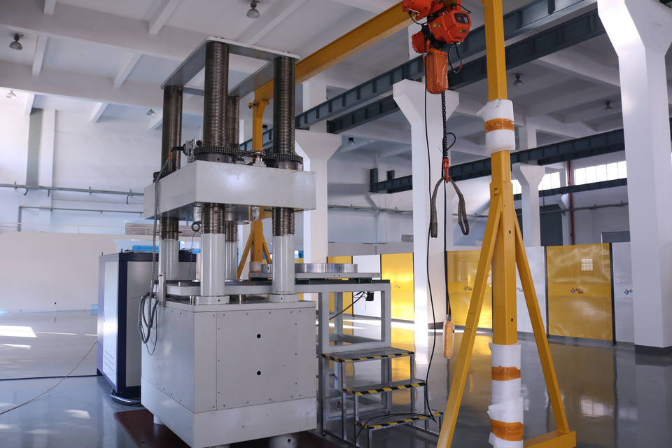
Large force-testing frame with an adjacent lifting gantry.
A New Calibration Milestone for the FIBOS FA4221-10MN
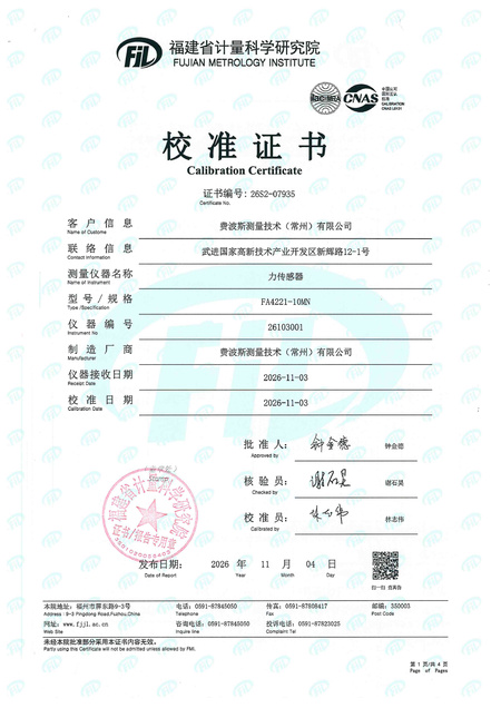
The calibrated instrument was manufactured by FIBOS Measurement Technology (Changzhou) Co., Ltd. and identified as FA4221-10MN, serial number 26103001. Fujian Metrology Institute issued calibration certificate No. 26S2-07935 on November 4, 2026. The certificate records compression measurements over 1,000–10,000 kN and cites ISO 376:2011 as the calibration method.
At this scale, units matter. 10,000 kN equals 10 MN, approximately 1,020 metric tonnes-force under standard gravity. The description '1,000-tonne-class' communicates the scale; the technical test values remain in kN and MN.
The milestone is a documented calibration of an actual FIBOS sensor at these loads. It gives engineers evidence beyond a nominal capacity designation.

Cover of calibration certificate No. 26S2-07935, issued by Fujian Metrology Institute on November 4, 2026.
Why Force Calibration at the 1,000-Tonne Scale Is Technically Demanding
Applying a large load is only one part of force calibration. The reference force must be established, transferred through a suitable loading arrangement, and compared with the sensor's output. At high capacities, the frame, loading surfaces, and fixtures must accommodate the force while maintaining an appropriate axial load path.
Contact geometry and alignment affect how force enters a sensor. Changes in seating or unintended bending can change the response, even when the applied axial force is nominally the same. Three factors therefore shape the quality of a high-capacity calibration:
Reference force: how the applied force is established and traced to SI units.
Load path: whether the frame, platens, and fixtures keep the force axial and the contact consistent.
Measurement procedure: repeat measurements and measurements at different rotational positions, which help characterize seating and alignment effects.
This makes the loading arrangement and measurement procedure important parts of the evidence, alongside the maximum force reached.

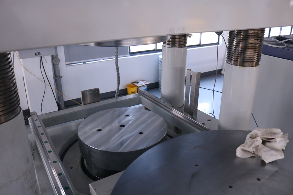
Close-up of the platen and working space within the force-testing frame.
Compression Calibration up to 10 MN: Test Points and Procedure
The certificate lists eight compression force points: 1,000, 2,000, 3,000, 4,000, 5,000, 6,000, 8,000, and 10,000 kN. Sensor readings were recorded in mV/V using a DMP-41 indicating instrument. The recorded environmental conditions were 22.8°C and 49% relative humidity.
The results table includes measurements at 0°, 120°, and 240°, with increasing-force and decreasing-force series where recorded. The mean values reported on the certificate (zero error corrected) are summarized below.
Table 1. Mean indications and relative expanded uncertainty by force point (certificate No. 26S2-07935, compression)
| Force (kN) | Mean increasing-force indication (mV/V) | Mean decreasing-force indication (mV/V) | Relative expanded uncertainty (%), k = 2 |
| 1,000 | 0.25335 | 0.24330 | 0.28 |
| 2,000 | 0.51072 | 0.49981 | 0.13 |
| 3,000 | 0.76791 | 0.75939 | 0.10 |
| 4,000 | 1.02435 | 1.01850 | 0.09 |
| 5,000 | 1.28020 | 1.27594 | 0.09 |
| 6,000 | 1.53535 | 1.53274 | 0.09 |
| 8,000 | 2.04166 | 2.04218 | 0.10 |
| 10,000 | 2.52178 | — (not recorded) | 0.11 |
At 10,000 kN, increasing-force readings are provided at all three positions; the corresponding decreasing-force entries are blank. The test therefore documents loading up to 10 MN without implying a complete unloading dataset at that endpoint.
These details help a project team compare its intended operating range and loading sequence with the conditions actually covered by the calibration. A machine that repeatedly approaches the same load from below may require a different assessment from one that relies on readings during unloading.
What the Calibration Results Mean for Force Measurement
At 10,000 kN, the reported mean increasing-force indication was 2.52178 mV/V. The relative expanded uncertainty at that point was 0.11%, with coverage factor k = 2. Across the listed force points, reported relative expanded uncertainties range from 0.09% to 0.28%.
These values describe uncertainty associated with the reported calibration results; they are not a single accuracy specification for every use of the sensor.
The certificate also reports five characteristic errors. Each answers a different question about the measured response, so they cannot be treated as interchangeable measures of accuracy.
Table 2. Characteristic errors reported on the certificate (compression)
| Characteristic | Reported value (%) | What it describes |
| Relative reproducibility error | 0.39 | Agreement between increasing-force series at different rotational positions |
| Relative repeatability error | 0.05 | Agreement between increasing-force series at the same position |
| Relative interpolation error | +1.20 | Deviation of readings from the fitted interpolation curve |
| Relative zero error | +0.01 | Change in the zero reading after loading |
| Relative reversibility error | 3.86 | Difference between increasing-force and decreasing-force readings at the same force |
For example, the repeatability error of 0.05% and the reversibility error of 3.86% describe very different behavior. For applications using both loading and unloading readings, the reversibility result deserves particular attention.
The certificate states that the results are traceable to SI units and public measurement standards. In practice, engineers should review the complete results against the required measurement tolerance, loading direction, and readout configuration. The data apply to the identified instrument under its calibration conditions; the installed measurement chain still needs project-specific verification.

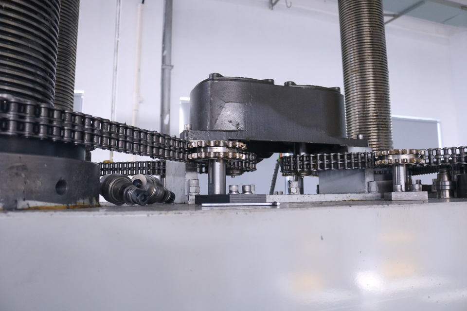
Detail of the chain and screw assembly on the testing equipment.
Where 10 MN Force Measurement Can Support Heavy-Load Projects
Heavy-duty presses, structural loading rigs, and large-component test systems are potential applications for high-capacity compression measurement. In each case, the useful question is how the sensor will receive the load and how its signal will support the test or process decision. Calibration data can inform that assessment, while mechanical suitability and operating conditions must be checked separately.
For equipment integration, an evaluation typically covers the following points:
Mechanical: working and peak loads, available installation height, contact dimensions, and expected off-axis forces.
Electrical: bridge excitation, signal conditioning, readout resolution, and data acquisition requirements.
Measurement: the smallest force change of interest, compared with the performance of the complete measurement chain.
Beyond this calibration: dynamic response and fatigue suitability require their own evidence; a static compression calibration does not cover them.

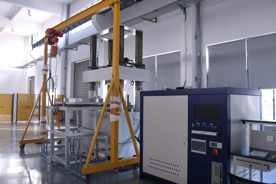
Force-testing frame with a control cabinet and lifting equipment.
Discuss Your High-Capacity Force Measurement Requirements with FIBOS
For a 1,000-tonne-class measurement project, start with the load requirement and the installation drawing. Sharing the following information helps the evaluation move quickly:
Working range and peak load
Loading and unloading sequence
Mounting space and interface details
Readout or data acquisition system
Acceptance criteria
For a replacement sensor: the original model and interface details
Contact FIBOS to discuss the FA4221-10MN calibration results and the requirements that need to be assessed for your application.