You are here:Home » Blog » Bending Beam Load Cells: Types, Applications, and How to Choose
Bending Beam Load Cells: Types, Applications, and How to Choose
Views: 0 Author: Site Editor Publish Time: 2026-11-20 Origin: Site
A bending beam load cell measures force from the elastic bending of a beam. It can suit a platform scale, hopper, or checkweigher when the equipment directs the load to the specified loading point and leaves the beam free to deflect.
Replacing a cell: Start with the existing part number, mounting drawing, and weighing input.
Designing new equipment: Define the maximum load per support and the smallest weight change the system must detect, then check mounting and electronics.
Is a Bending Beam Load Cell Right for Your Equipment?
· How Bending Beam Load Cells Measure Weight
In a common arrangement, one end is fixed to a rigid base and the equipment applies a force to the other end. As the beam bends, strain gauges in the sensing region stretch or compress.
As the resistance of the gauges changes, the powered Wheatstone bridge produces a small differential voltage. A weighing instrument uses calibration to convert that signal into a displayed weight or mass.
A simple single bending beam responds to bending moment, so moving the same load along the beam can change the output. Double- and multiple-bending-beam designs can reduce this sensitivity. Use the model drawing to locate the permitted loading point and direction.
The downward load bends the free end. Strain gauges near the fixed end detect the resulting strain. The dashed line shows the unloaded position, and the deflection is exaggerated.
· When to Use a Bending Beam Load Cell in a Platform Scale
A platform supported at several points can use beam load cells when the frame transfers each support reaction through its designated loading point. Check the heaviest corner or edge loading condition as well as a centered load.
If one sensor will support the entire deck and products can land away from center, look for a single-point load cell with a specified maximum platform size and off-center load performance. The load cell selection guide covers other mounting arrangements.
· What Changes for Hopper Weighing and Dynamic Checkweighing?
For a hopper, check the following conditions:
Support reactions: Calculate the reaction at each support with the hopper loaded.
Pipework and restraints: Check whether they resist vertical movement.
Filling impact and thermal expansion: Include these conditions, where applicable, when evaluating the cell and its mounting hardware.
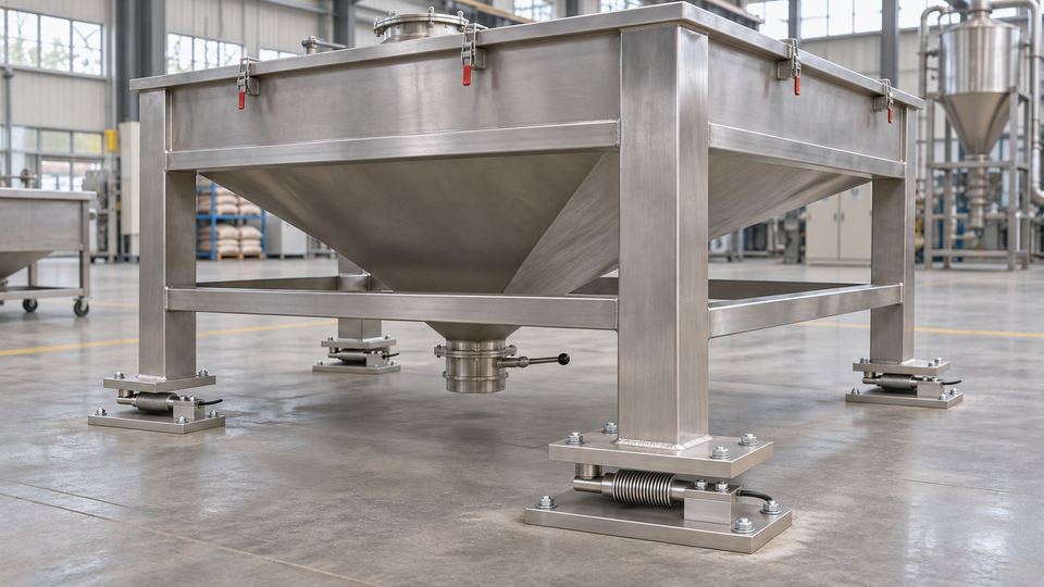
Hopper weighing application illustration. Each leg is bolted to an upper mounting plate. The horizontal bending beam transfers the load to the anchored base plate.
A dynamic checkweigher takes readings while each package moves across the weighing section. Belt vibration, package spacing, and the time available for sampling and filtering affect the result.
Use static calibration as the starting point. Then measure error and repeatability with representative packages at the intended line speed.
What Capacity and Accuracy Does Your Equipment Need?
· Size Each Load Cell for Dead Load, Product Weight, and Peak Loads
Estimate the load each cell carries from the deck, fixtures, and heaviest product. In a multi-cell scale, calculate the greatest support reaction across expected product positions and allow for peaks from transfer or filling at the affected supports.
Compare the worst operating load with the rated capacity. Check the datasheet's separate safe overload limit for exceptional loads.
For example, a single cell carries a 4 kg fixture and up to 12 kg of product, for a static load of 16 kg. If the largest expected transfer peak adds the equivalent of 2 kg in the measuring direction, the total is 18 kg.
A 20 kg cell is a candidate, leaving 2 kg between the assumed peak and rated capacity. Whether that is enough depends on how reliably the peak is known and how much the operating conditions vary.
· Check the Smallest Weight Change Your System Must Detect
Suppose the same machine must distinguish a 10 g weight change. With a nominal sensitivity of 2 mV/V and 5 V excitation, the full-scale signal span is 10 mV.
Ideal signal change for a 10 g increment
Rated capacity
Ideal signal change
20 kg
10 mV × (0.01 kg ÷ 20 kg) = 5 µV
50 kg
10 mV × (0.01 kg ÷ 50 kg) = 2 µV
With the same sensitivity and excitation, the larger cell carries more load but produces a smaller signal for the same weight change. Use the estimate to check the bridge input, then verify that the assembled machine can distinguish the change.
Run the test with the actual cable, filter settings, and operating cycle.
Choose representative working loads and record the baseline readings.
At each load, add and remove 10 g repeatedly and record the readings.
Compare the observed change with the spread of readings and check whether the two load states are consistently distinguishable.
A display that increments by 10 g establishes the display interval. The repeated test establishes whether the machine can reliably distinguish that increment under the tested conditions.
· Account for Repeatability, Creep, and Temperature Effects
Match each specification to a condition in the machine:
Repeatability: Repeatedly weighing the same part across cycles.
Creep: Taking a reading after a full hopper has stayed loaded for a period.
Temperature effects: Operating through machine warm-up or a wide ambient temperature range.
If the scale must meet an error limit over its working range, also check nonlinearity and hysteresis. Use the datasheet's reference basis to convert percentage errors into weight equivalents. Verify the assembled system against the process tolerance.
Will the Load Cell Fit Your Mounting and Controls?
· Check the Mounting Drawing, Load Direction, and Clearance
Overlay the load cell drawing on the machine layout and check:
The fixed-end hole pattern and the loaded-end hole or contact point.
Installed height and space for tools and cable routing.
Load direction, following the arrow on the model drawing.
Keep brackets and guards clear of the bellows and loaded end throughout the expected deflection, including at full load.
· Check the mV/V Output, Excitation, and Weighing Input
A passive mV/V cell needs excitation and a differential bridge input. If the controller expects 4–20 mA or a digital value, select a compatible weighing transmitter or controller module.
Check the following on the instrument or module:
Excitation voltage range and bridge input range.
Sample rate and filter settings for the intended operating cycle.
For a six-wire cell, match excitation, signal, sense, and shield to the wiring diagrams. Sense leads allow a compatible instrument to compensate for changes in excitation voltage at the bridge.
The catalog shows EXC+ as blue for FA510 and green for FA544. Match wires by terminal function using the wiring diagram for the exact version ordered.
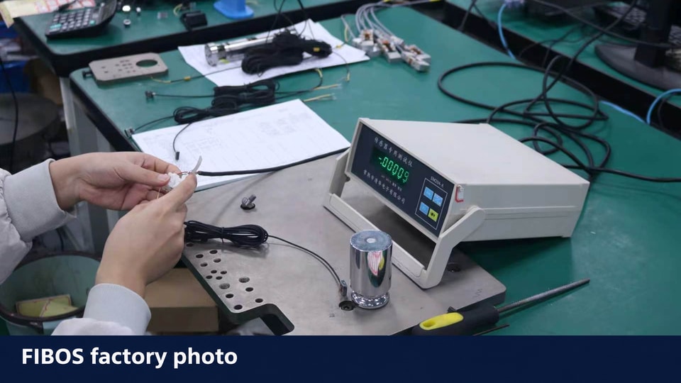
Sensor wiring and instrument testing at a FIBOS factory workstation.
· What Must Match When Replacing an Existing Load Cell?
Before ordering, record the old part number, capacity, and drawing revision. Check compatibility in three areas:
Mechanical: Installation dimensions, load direction, and loading interface.
Electrical and environmental: Sensitivity, excitation, terminal functions, temperature limits, and ingress protection.
Multi-cell scales: Compatibility with the remaining cells, junction box, and weighing instrument before replacing only one cell.
During installation, confirm the wiring by terminal function even if the cables look alike. After replacement, recalibrate the complete scale.
Which FIBOS Bending Beam Load Cell Should You Evaluate?
· FA510 and FA544: Compare the Specifications and Mounting Drawings
The FIBOS FA510 and FA544 are stainless-steel beam load cells with protective bellows. The FIBOS 2026 catalog shows compression loading in the illustrated arrangement for both models.
Specification
FA510
FA544
Rated capacity options
5, 10, 20, 50, 100, 200, 500 kg
5, 10, 20, 50, 75, 100, 200, 300, 500 kg
Nonlinearity
0.018% F.S.
0.02% F.S.
Ingress protection
IP68
IP68
Excitation voltage
5–15 V DC
5–12 V DC
Operating temperature
−30 to +70 °C
−20 to +60 °C
Source: FIBOS 2026 product catalog, FA510 p. 104 and FA544 p. 109, with nonlinearity expressed as percent of full scale on the product pages.
Check the enclosure, junction box, and cable terminations separately for the installed environment.
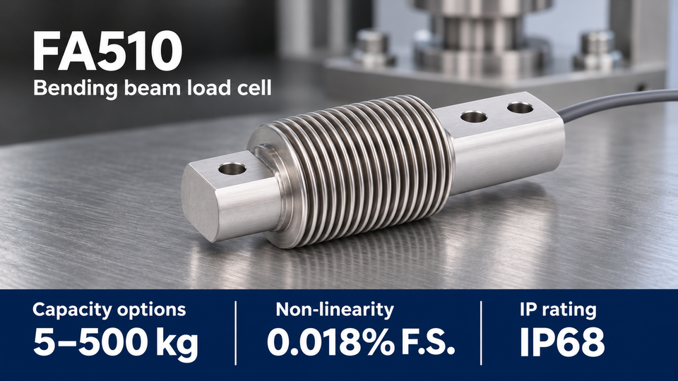
FIBOS FA510 product illustration and catalog specifications. See the table for individual capacity options.
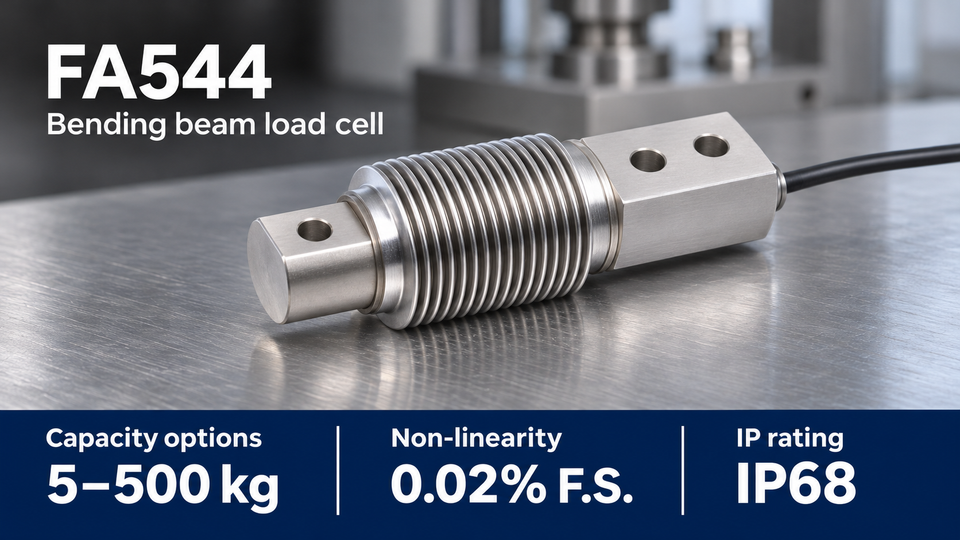
Both drawings show a 123 mm body length. The end geometry differs, so check the hole diameters and mounting drawing for the capacity ordered before finalizing the bracket or replacing an existing unit.
FIBOS FA544 product illustration and catalog specifications. Confirm the mounting drawing for the capacity ordered.
· What to Confirm Before Ordering a Sample or Production Batch
Send the following details with your inquiry:
Equipment drawing or current part number.
Maximum load per cell and target weighing tolerance.
Weighing instrument model and expected quantity.
For a sample, confirm the drawing and wiring revisions, necessary mounting parts, sample price, and estimated ship date.
For production, confirm quantity pricing, manufacturing lead time, delivery terms, included documentation, warranty, and the process for getting application or replacement support.
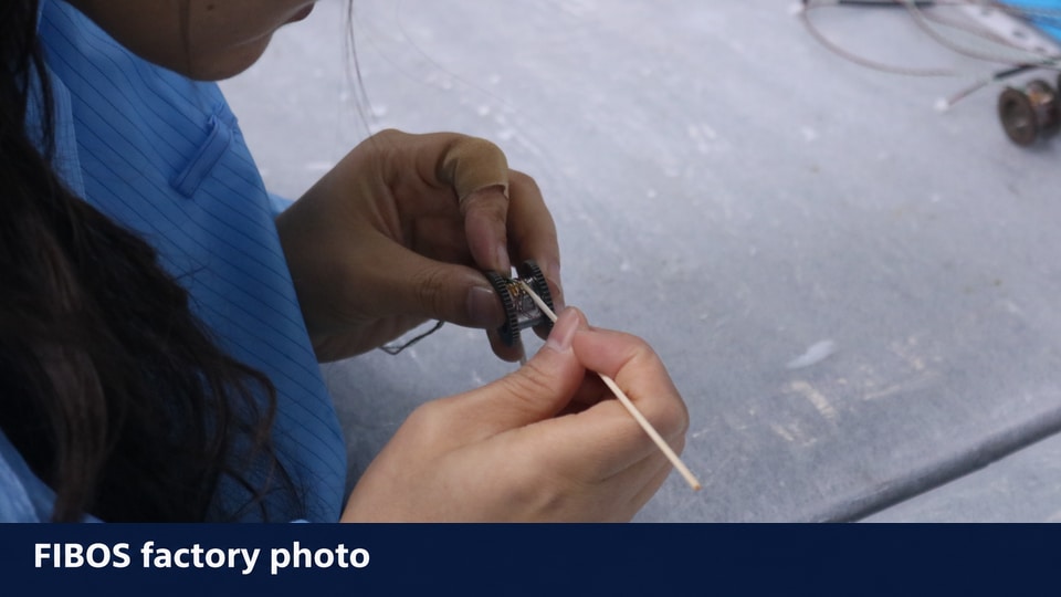
Manual work on a sensor component at a FIBOS assembly bench.
How Do You Verify the Weighing System After Installation?
· Check for Side Loads, Binding, and Load Bypass
Check that the platform or vessel rests on its intended supports and moves freely within the specified clearance. Look for common sources of side load or load bypass:
Taut cables or rigid piping.
A guard touching the deck.
A stop that engages during normal weighing.
If the same test weight gives different readings at different positions, locate the cause before adjusting the span or corner trim.
· Use Known Loads to Check Calibration, Repeatability, and Return to Zero
Perform the checks with the equipment in its normal operating configuration. Follow the weighing instrument manual for zero and span calibration.
Start empty, set zero, and calibrate span using the method specified for the instrument.
Verify the reading with known loads at several points across the working range.
Reapply a representative load several times. Record the spread of readings and check the empty reading after each unload.
Check the conditions specific to the machine. On a platform, move the same test load to the expected loading positions. On a checkweigher, repeat with representative products at the required speed.
Compare the results with the equipment acceptance limits.
Frequently Asked Questions
1. Can a Bending Beam Load Cell Measure Both Tension and Compression?
Some beam designs support both directions with the specified fixtures and calibration. Check the load arrow, directional ratings, and mounting hardware for the exact model. The FA510 and FA544 catalog drawings show compression for the illustrated installations.
2. Is a Bellows Load Cell Always a Bending Beam Load Cell?
No. The bellows describes the protective enclosure around the sensing region. Identify the measuring structure and loading direction from the model datasheet and drawing. The bellows cover itself should be kept clear of external contact.
3. Does Taring the Scale Free Up Load Cell Capacity?
No. Taring resets the displayed net weight. The fixture, empty vessel, or product already on the scale continues to load the sensor. Use the gross load and the worst support reaction for the capacity check.
4. Can You Use an Existing Junction Box With a Replacement Load Cell?
Possibly. Check whether it is a passive summing box or an active digital box, then verify the input type, wiring, and trim method. In a passive multi-cell system, confirm that the replacement's output and bridge characteristics are compatible with the remaining cells and the instrument. Check corner readings and recalibrate after installation.
5. Why Does the Hopper Reading Change After the Piping Is Connected?
Piping can support some of the hopper weight or push or pull on the vessel. Its effect can vary as the hopper fills or heats up. Compare zero and known-load readings before and after connection under controlled commissioning conditions. If the readings move outside tolerance, review pipe support, alignment, and flexibility with the equipment designer.