You are here:Home » Blog » Shear & Cantilever Beam Load Cells: Types, Applications, and How to Choose
Shear & Cantilever Beam Load Cells: Types, Applications, and How to Choose
Views: 0 Author: Site Editor Publish Time: 2026-11-19 Origin: Site
A shear beam load cell measures an applied load through shear strain in its sensing section. A cantilever beam load cell is fixed at one end and loaded toward the free end. A single-ended shear beam can be both. You can also mount a bending beam as a cantilever. For a scale or process vessel, start by tracing how the weight reaches each sensor and how much load the most heavily loaded support will carry.
What Are Shear Beam and Cantilever Beam Load Cells?
Both are commonly used to measure the component of force along the load cell's rated direction. In a typical floor scale, that component is vertical. The indicator uses the calibrated signal to display a mass reading. A side force or a load that reaches the frame through another contact can change that reading.
For a cantilever installation, identify which end bolts to the structure and where the load or support reaction acts at the opposite end. A typical double-ended shear beam has supports at both ends and receives the load near the center. Follow the drawing for the actual model and weigh module. Rice Lake load cell handbook
How Do Shear Beam and Bending Beam Load Cells Work?
· Shear Strain in the Beam's Thin Web
Many shear beam designs have recesses machined into the sides, leaving a thin vertical web. In the sensing region, gauges oriented at about +45° and −45° to the beam's longitudinal axis respond to the tensile and compressive strains associated with shear. Their resistance changes are combined in a bridge circuit.
· Tensile and Compressive Strain in a Bending Beam
A bending beam is shaped to concentrate bending strain in defined areas. Gauges in regions under tension and compression change resistance as the beam bends. A change in the load position can change the bending moment, so use the contact point or loading interface shown on the drawing. Some designs use multiple flexures to control sensitivity to load position.
· How the Wheatstone Bridge Produces an mV/V Output
A regulated excitation voltage powers the Wheatstone bridge. Loading changes the gauge resistances and creates a small differential voltage. Rated output in millivolts per volt (mV/V) is the signal change from zero load to rated load divided by the excitation voltage. For example, a cell rated at 2.0 mV/V with 5 V excitation gives a nominal signal change of 10 mV at rated load.
Which Beam Configuration Fits Your Application?
Choose the support and loading arrangement before comparing individual datasheets. Start with the equipment frame, the available height, and where the load can enter the beam.
· Single-Ended Shear Beams for Floor Scales and Process Weighing
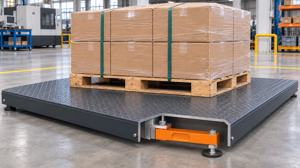
When a pallet is placed on a low-profile floor scale, the platform transfers its weight to the corner cells. In a common foot-mounted configuration, each single-ended shear beam bolts to the underside of the deck at its fixed end. A leveling foot connects the opposite end to the floor. Check the clearances under load so the deck stays clear of the surrounding floor or frame.
Floor scale application. The corner cutaway shows a single-ended shear beam between the deck and a leveling foot.
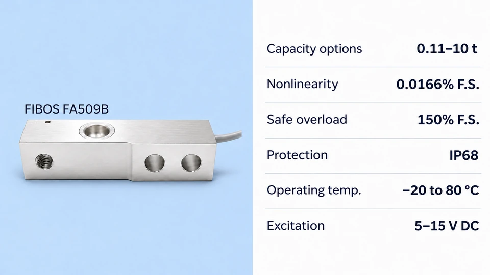
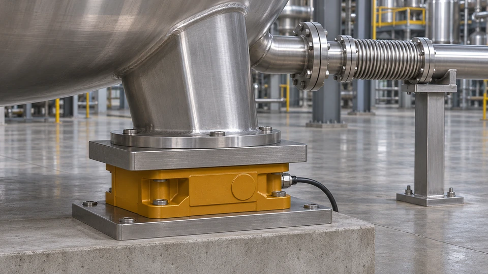
For process equipment, a compatible weigh module can define the load path between the vessel leg and the base. The FIBOS FA509B is a cantilever-mounted compression load cell with a 17-4PH stainless steel sensing element. Its catalog lists eight rated capacities: 0.11, 0.22, 0.55, 1.1, 1.76, 2.2, 4.4, and 10 t.
FIBOS FA509B product illustration based on the official product photo. Mounting dimensions depend on the selected capacity.
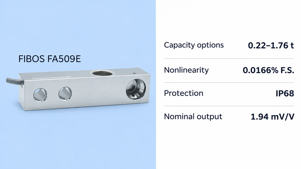
The FIBOS FA509E is another cantilever option. Its installation drawing shows one cell at each corner and a floating load button between the deck and the beam. The published capacity range is 0.22–1.76 t, with 0.0166% F.S. nonlinearity, IP68 protection, and 1.94 mV/V nominal rated output.
FIBOS FA509E cantilever load cell. The installation drawing shows a floating load button.
· Double-Ended Shear Beams for Truck Scales, Tanks, and Hoppers
On a truck scale with double-ended shear beams, the truck tires load the weighbridge deck. At each sensor location, a load introduction assembly transfers the local deck reaction near the beam's center. Seats at both ends carry that reaction into the foundation. Check how the mounting system accommodates longitudinal forces from vehicle braking and movement of the deck.
Truck scale application. In the cutaway, the deck transfers load to the middle of a beam supported at both ends.
Tanks and hoppers can also use this arrangement where the frame has room for two end supports and the specified center-loading hardware. Check the movement needed for vessel expansion.
· Bending Beam Designs for Lower-Capacity Weighing
Consider a bending beam for compact batching or dosing equipment when its available capacities, deflection, and mounting arrangement suit the machine. If one cell must support an entire platform and the product can land off-center, evaluate a single point load cell with a specified platform size and off-center performance. Bending beam and shear beam capacity ranges can overlap, so use the actual models' specifications.
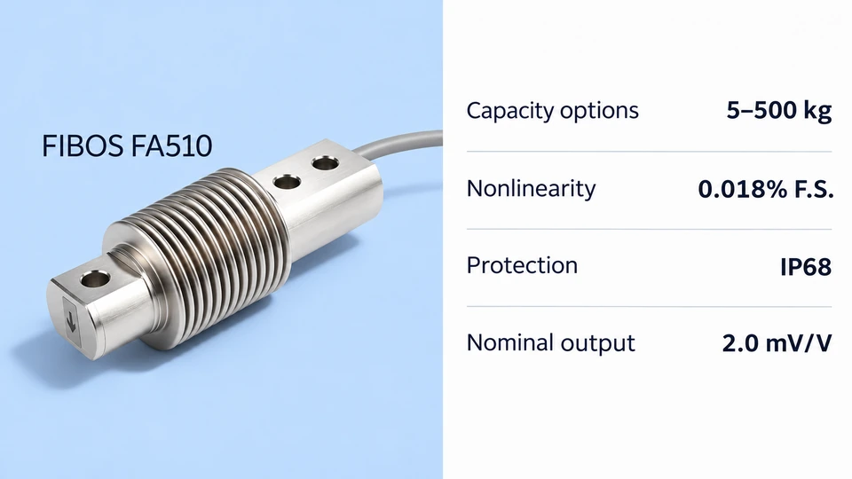
The FIBOS FA510 is a welded-seal stainless steel bending beam for applications such as packaging scales and hopper scales. It offers capacity options from 5 to 500 kg, 0.018% F.S. nonlinearity, IP68 protection, and 2.0 mV/V nominal rated output.
FIBOS FA510 welded-seal bending beam for lower-capacity weighing.
How Do You Choose the Right Load Cell Capacity and Specifications?
· Estimate the Maximum Load at Each Support Point
Size for the most heavily loaded support. Include the dead weight of the vessel or platform and attached equipment, maximum payload, and how the material shifts during filling or discharge. Estimate operating peaks if the application involves impacts or moving loads.
For a four-support vessel, suppose the empty vessel weighs 600 kg and the maximum payload is 1,400 kg.
Gross load = 600 kg + 1,400 kg = 2,000 kg.
Equal share = 2,000 kg ÷ 4 = 500 kg per support.
Worst support in this example carries 35% of the gross load. 2,000 kg × 0.35 = 700 kg of static load, expressed as equivalent mass.
Use 700 kg as the starting point for that support, then account for operating peaks and applicable design margin. The 35% share is an assumed result for the example. Determine the actual share from your structure and load cases.
Taring removes the empty vessel weight from the display. The vessel still loads the sensors. Check abnormal peaks against the cell's safe overload and the mounting hardware limits separately.
· Check Measurement Error at Your Smallest Required Weight
Start with the smallest amount you need to weigh and the allowable error in grams or kilograms.
For example, a single cell rated at 1,000 kg with nonlinearity specified at 0.02% of full scale has a nonlinearity limit equivalent to 1,000 kg × 0.0002 = 0.2 kg. This is one error contribution from one cell. The uncertainty at a particular reading depends on the complete installed system.
Allow for repeatability, hysteresis, creep during hold periods, temperature effects, mechanical friction, and instrument noise as relevant. Test near the smallest working load to see whether the system can reliably resolve the required change, even if the display shows fine increments.
· Match Materials and Sealing to Washdown, Corrosion, and Temperature Conditions
Check the beam alloy, sensing-area seal, cable entry, and junction box for the actual environment. For washdown, confirm the specified ingress test and how it compares with the cleaning pressure, water temperature, and chemicals used on site. Check the operating temperature range and the compensated temperature range separately, especially near hot tanks or where equipment is washed between shifts.
How Do You Install Beam Load Cells for Accurate Weighing?
· Check the Mounting Surface, Fasteners, and Load Direction
Use the model's installation drawing before fitting the sensor. Support the platform or vessel independently during assembly, and keep the load cell within its installation limits throughout the work.
Mounting surface. Check that the foundation is flat and rigid and that the fixed end seats fully.
Fasteners and load direction. Verify bolt grade, tightening torque, and the specified loading point and direction.
Operating clearance. Keep the active beam and loading end clear of unintended contact, and recheck clearance with the equipment loaded.
· Account for Side Loads, Thermal Expansion, and Forces from Piping
A vessel may move slightly as it fills or warms up. Rigid piping, tight conduits, a rubbing guard, or a restraint that engages too early can redirect part of the load or introduce side force. Check the layout at cold and hot conditions and across the fill range. Support connected piping independently where appropriate and assess the force it still transfers to the vessel, including any pressure thrust from flexible connections.
Vessel weighing illustration showing the load path through the weigh module and separate support for the connected pipe.
· Decide When to Use a Weigh Module
Consider a weigh module when the installation must accommodate horizontal travel, provide controlled load introduction, or incorporate lateral restraint or uplift protection. Check which features the chosen module provides and their ratings. On a multi-leg vessel, confirm how each support is allowed to move and where restraint acts. Verify the arrangement against the system's expected loads and movements.
How Do You Connect and Verify the Installed Weighing System?
· Match Bridge Excitation and mV/V Output to the Weighing Indicator
Confirm that the indicator or signal conditioner can supply the load cell's excitation voltage and read the expected millivolt signal from the dead load through the working span. Follow the sensor and instrument wiring diagrams for excitation, signal, sense leads where fitted, and shield termination. Wire colors can differ between models. When connecting a PLC, check whether it has a strain-gauge input or needs a transmitter or weighing module for signal conversion.
· Calibrate the System and Check Zero, Span, and Load Distribution
Before calibration, confirm the final mounting and all normal operating connections. Follow the equipment's validated procedure and use reference loads suited to its working range.
Check load distribution. On a multi-cell platform, move the same calibrated test load to the specified positions. Correct mechanical unevenness or contact first. Then trim the cell outputs if needed and supported.
Calibrate zero and span. Set them after the mechanical checks and applicable balancing.
Verify the result. Check zero return after unloading, repeatability, and response near the smallest working load. Check position-dependent error on a platform where applicable. For a vessel, compare readings with a suitable reference under representative operating conditions.
Record the reference load, its position where applicable, and the test conditions so you can reproduce the check.
Frequently Asked Questions
1. Can I replace a bending beam load cell with a shear beam load cell?
Sometimes. Compare the original and candidate drawings for bolt pattern, mounting height, load contact geometry, load direction, and clearance. Then check capacity, rated output, excitation, bridge resistance, and wiring. Verify response and calibration after installation. On a multi-cell scale, also check how the replacement behaves alongside the other cells before trimming and recalibrating.
2. How does a single-ended shear beam differ from a single point load cell?
A single-ended shear beam describes the sensing method and the way the beam is supported. A single point load cell is designed to support a platform on one cell and limit position-dependent error under stated conditions. If the load can move across the platform, look for a specified platform size and an off-center performance specification.
3. Can I size each load cell by dividing the total weight by the number of supports?
That gives the average reaction for an evenly loaded system. Use it as an initial estimate, then size for the most heavily loaded support under the expected loading cases. Check for uneven fill, an offset center of gravity, out-of-level supports, and temporary loading during filling, discharge, or maintenance.
4. Can I connect multiple analog load cells to one weighing indicator?
Yes, if the cells and indicator support the arrangement. A common approach uses a compatible summing junction box. With bridges wired in parallel, confirm that the combined input resistance stays within the indicator's excitation drive limits. For example, four identical 350 Ω input bridges in parallel present about 87.5 Ω, ignoring wiring and trim resistances. Check the terminal's load limit and calibrate the assembled scale.
5. Why does a tank's weight reading change after the piping is connected?
The pipe may carry part of the tank's vertical load or push or pull on the vessel as it fills, changes temperature, or becomes pressurized. A zero adjustment can remove a constant offset at one condition. To find load-dependent error, compare readings with a known load or other suitable reference across representative conditions, then inspect pipe alignment, supports, and connection movement.